RTTY Modem

Matt Roberts - matt-at-kk5jy-dot-net

Published: 2016-09-29

Updated: 2018-07-01


This article is for the original version, based on the Arduino Uno.  For the version 2.0 modem, based on the Teensy, see the Version 2.0 article.

QRP for Computers

To be honest, I think the idea of HF QRP is very interesting.  Just like the guys who fly gliders, the QRP community continues to master the art of doing more with less, and I admire their accomplishments.  I am not patient enough to do QRP at the moment, but I am taking some inspiration from their idea of optimizing the power budget of a radio station.

If I ever found myself operating with a power budget, I would rather put the power I have into the transmitter, or into the longevity of operation.  I see no reason to run 5W or less from the transmitter, when the PC used for digital modes or logging burns 400W or more, even when idling.  I would much rather run the computer and interfaces "on QRP," and then have 400W of input to my transmitter, giving me a 200W signal on the air.  That would give me nearly three S-units of improvement at the other guy's receiver, without one more watt of power consumed!

Unfortunately, the modern sound-card-mode software requires ever-increasing CPU power to run accepably.  While the DSP capabilities of these packages is indeed impressive, it is a bit over the top for casual or portable operating, where a simple text-to-mode interface would be more than sufficient.  I have successfully used small low-power computers for modes such as BPSK31 and CW, so I have been working to see how much digital mode functionality I can squeeze out of a microcontroller such as the Atmel AVR, upon which the Arduino line is built.

This approach worked quite well for the CW modem project, so I thought I would try another digital mode -- this time, RTTY.  This mode turned out to be even simpler to implement on an Arduino than CW, and the project gets me one step closer to my goal of having an open-source, multimode digital interface for HF that can be run completely from battery, and does not require a PC with a soundcard.

The main idea for both projects is to provide a modem that can be used with a simple terminal program.  The modem converts the characters being typed in the terminal into outgoing data in the chosen mode, to modulate the radio.  It also decodes the audio signals from the radio and converts these into readable text.

The Hardware

Hardware
Figure 1: RTTY Prototype Hardware
Like the CW modem, the hardware for the project controller includes a few essential elements:
The first prototype hardware is shown in Figure 1.

The Decoder Circuit

For this project, I chose the NJM2211D to provide FSK demodulation.  This part is still in production, and is a rather versatile circuit.  The device requires a small part count, and operates from a humble 5mA of current at 5V supply, which is less current draw than many LEDs.  The circuit can operate with a center frequency near 300kHz, which makes it a generic receiver circuit for FSK or FM demodulation.  Looking at the data sheet, the circuit's specifications mean that it could almost be used as a complete receiver for CW or FSK, for RF signals below 300kHz, if desired.

2211 Schematic
Figure 2: Modified 2211 Schematic
As shown in Figure 2, the circuit has three different outputs: two are Q outputs, which are driven low when the detector's PLL is locked; and a single FSK output.  The two Q outputs are complementary, with one being driven low when the PLL is locked, and the other when the PLL is unlocked.  All three outputs are open-collector, which means that an external pull-up resistor is needed.  The Arduino can provide this internally to the CPU, but I chose to provide pull-up resistors everywhere that the datasheet calls for them, just to keep the logic states stable at all times.  The outputs can only sink 5mA of current, so care is needed when using them to drive LEDs.

The 2211 is "programmed" through a handful of analog passive components, and its parameters include center frequency, bit rate, frequency shift and detection bandwidth.  Example circuits are somewhat difficult to find on the internet, but the NJM data sheet contains several examples and a relatively detailed design strategy.  In the simplest configuration, the FSK output pin is brought to an input pin on the controller, so that the receive data can be read.  I chose to wire one of the Q outputs to an LED as a tuning aid.

This circuit has some of the same challenges as LM567 designs in the CW modem project, the biggest being stability.  The circuit uses a VCO which is very sensitive to voltage stability and quality of the electrical connections to the IC.  My original circuit build was on a breadboard, but keeping it stable on the breadboard was a challenge.  Additionally, the 5V rail from the Arduino can be quite noisy, and requires considerable filtering when driving an analog circuit.

Improving the Hardware

I rebuilt the FSK demodulator onto a perfboard as shown on the right-hand side of Figure 3.  This project board is designed to plug directly onto the headers of an Arduino UNO, and has enough room for a circuit of this size and part count.  The solder construction stabilized the decoder nicely, and made the tuning more stable.  The potentiometer I chose still required some careful adjustment.  If I build another board, it will use a multiturn trimmer, to make adjustment of the center frequency easier.  Nonetheless, a soldered-together board worked flawlessly on fldigi-generated test signals.

Hardware
Figure 3: Updated Hardware
 
Hardware
Figure 4: AFSK Transmit Filter
With the demodulator moved onto the shield board, the breadboard was free for experimenting with transmit filters, as you can see on the left-hand side of Figure 3.  The schematic for the filter is shown in Figure 4.  When configured for AFSK output, the data output pin generates a square-wave AFSK signal.  In order to be usable for connection to a transmitter, this signal must be filtered to convert it into a clean sinusoid.  Further, the 0V to +5V square wave has a substantial DC offset, which must be removed in order to eliminate very low frequency transients when the tone starts or stops.  After some experimentation with TL082 op-amps, I found that a single first-order passive high-pass filter followed by a fourth-order active low-pass filter provided a very clean output signal, with the DC bias removed.  For this project, I chose a center frequency of 1000Hz, because I prefer to hear RTTY signals centered around that frequency.  However, a 1500Hz or 2000Hz center frequency would be a better choice, because the output filter would not need to be so aggressive, since the radio's transmit audio filter would do most of the work for me, both HPF to remove the DC bias, and LPF to make the sinusoid clean.  Nonetheless, it is good to inject a clean signal into the radio, regardless of the amount of filtering needed to achieve that, to keep the on-air RTTY emission spectrally pure.  When I move this circuit onto a prototype board, I will probably use a TL084, in order to have all four op-amps in one package.

The op-amps had the same struggle with voltage stability that the demodulator circuit had.  Bypassing the V+ with an 0.1uF cap did the trick for the Vcc+ rail.  However, I used a resistive voltage divider to feed the non-inverting inputs of the op-amps, to center the amplifiers with a +2.5V reference, in order to avoid needing a split supply.  Resistive dividers have their own challenges, but in this case, the divider greatly increased the effect of V+ rail noise on the non-inverting input, producing substantial output noise.  To cure this, I added a 4.7uF electrolytic cap from the center of the divider to the GND rail, to hold the 2.5V reference voltage steady.  Typical bypass cap values just didn't get the job done, but 4.7uF did the trick.  This was yet another reminder that the +5V on the Arduino units can be quite noisy, and needs to be compensated when used to feed analog circuits.

Connecting an LED to the inverted Q output provides a tuning aid for adjusting the board.  Using the fldigi "TUNE" function to emit a single tone at the intended center frequency of the VCO, the potentiometer is adjusted until it is in the center of the range that lights the LED.  Then fine tuning can be done if needed to obtain the best copy for the given tone shift.  Once this is done, it should not be necessary to repeat the process.  I am hoping to use the voltage offset obtained by one of the comparator input pins to build a multi-LED tuning indicator that will help adjust the radio frequency during operation.

I added some header pins pointing upward away from the top of the board, so that I can adjust which demodulator outputs are assigned to which Arduino pins.  This is obviously not required, but is just a nice feature for me to use for experimentation.

This 2211 circuit can also be used for CW operation, with the Q output used as the detector output.  Whenever tone is present at the center frequency of the decoder, the PLL will lock, and the Q line will be asserted.

The Firmware

The firmware consists of a simple program or "sketch" that does the timing and decoding functions.  It uses logic-level input and output pins to receive and send the RTTY data.  The choice of pins can be selected at the top of the sketch.  Each setting is well-documented with comments in the sketch, and a value of zero (0) will disable optional pins.

For transmission, there are two options.  The first option is to use a digital output pin to drive the FSK input of a transciever; in this mode, the transciever generates the tones.  The second option also uses a digital output line, but to generate a square-wave FSK signal.  This waveform can be passed through a quality low-pass filter to create a clean audio FSK waveform, and then passed to the transmit audio input of the transciever.  Between these two options, the modem should be compatable with any HF radio.

Two output pins are used to control sending.  One will control the PTT line of the radio, while the other generates the output data, as described above.  The PTT output should be used to drive a FET or BJT for T/R control of the radio.  This is a very standard keying interface scheme.  For those who are accustomed to using the VOX function of their radio (or the VOX function of a SignaLink) for T/R control, the PTT line can be disabled when AFSK output is configured.

Likewise, two input pins are used for reception.  The first was described above, which is the logic-level output of the FSK demodulator.  The second pin is an optional input, that can read the inverted Q line from the demodulator.  While not needed for proper demodulation, this signal can be used to signal the Arduino as to when the PLL is locked, and hence, when there is a real signal being decoded, rather than just noise.  This can effectively squelch the receiver, to prevent random characters from being printed when there is no FSK signal present.

Operation

Operating the unit is straightforward.  Just connect to the controller through a serial terminal program or the serial monitor in the Arduino environment.  When you type characters, the transmitter is enabled, and the modem will send the text you type.  When you are done typing, the radio will automatically go back into receive mode after a short delay, and the decoder will attempt to decode incoming characters.  This is very VOX-like operation.  For those who are familiar with CW operation, the behavior is similar to semi-QSK.

The command interface is documented below, and commands can be sent inline with the text.  When a proper #command; sequence is sent, the terminal will respond appropriately.  E.g., sending #UOS; might return a response of #OK:UOS=1;.  If a bad command is typed, e.g., #DOG;, the terminal returns #ERR:DOG;.  Any characters sent to the controller outside of the "hash-semicolon" wrapper are interpreted as text to send.  Characters sent from the controller to the PC outside of the wrapper should be treated as received text from the decoder.

The current firmware provides several command and configuration messages: The idea of the command interface is to provide a way to make it easy to integrate into another application, but straightforward enough to be used from a so-called dumb terminal application.

Hardware
Figure 5: NJM2211 on
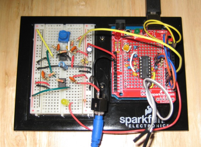
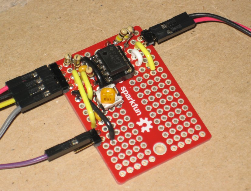
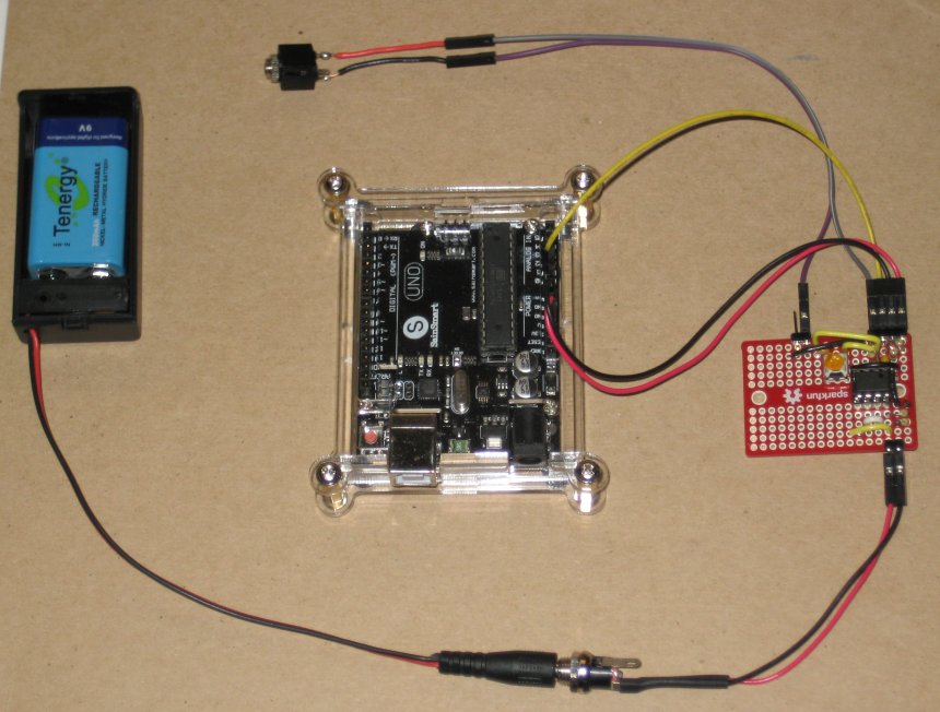
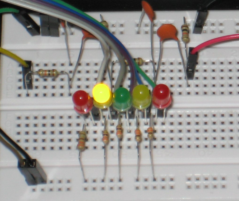
Solderable Breadboard
 
Hardware
Figure 6: New 2211 Circuit
with SainSmart UNO
First Impressions

The firmware sends and receives 45.45bps RTTY flawlessly when connected back-to-back with another modem, or a PC running Fldigi.  An on-air test is definitely the next step, since the controlled tests have worked out well.

Why have one when you can have two?

The demodulator circuit worked well on the shield board, but the shield board has one drawback.  This is a perfboard, with plated holes, but there are no traces between any of the holes.  There is one +5V rail, and one GND rail, with several holes each, but any other connections between components of your circuit have to be added using jumper wires, which involves bending leads to connect adjacent holes.  This makes it difficult to change the value of components to experiment with different values for timing-critical items.

I made a third circuit, but this time, I built it on a so-called solderable breadboard.  This type of board is also a perfboard with plated holes, but each row of pins has a trace connecting them all together.  Many of you will probably remember similar boards that used to be available from Radio Shack.  These boards are meant to hold one or more small DIP parts and support components.  Each trace connects to one pin on the DIP component, and allows easy connection of several component leads to that pin by simple point soldering.  This has allowed me to experiment with different timing capacitor values, to optimize the board for specific shift, center frequency, and bit rate.  The updated board is shown in Figure 5.

The board shown is the "mini" version of the solderable breadboard.  The same manufacturer makes a larger board, approximately double the length, and with bus traces down the sides, that is meant to be the same layout as a traditional breadboard, but with solder contacts rather than pressure contacts.  That board could easily hold the 2211 circuit, and a quad op-amp for transmit filtering to make the entire analog section of the modem on one board with all of the support components.  Time permitting, I may build one and post pictures.

The Digital Approach

I recently found an article describing how to configure the A/D of the Arduino's AVR controller, so that it would sample at a regular interval.  Properly configured, this can be done at a rate useful for reading audio signals from the A/D.  This isn't hi-fi audio -- it only allows 8-bit unsigned readings, and the available sample rates are very nonstandard (e.g., 9615Hz, 19231Hz, ...).  However, for frequency-modulated mode such as RTTY's FSK, I thought this might be good enough to receive RTTY data directly into the unit without the need for an analog demodulator chip.

Sure enough, with a little tinkering, the Arduino can be made to read AFSK directly from the line-out of my PC running Fldigi.  The decoding quality is actually quite good.  I even used the same code to do simulations on my PC, and the software demodulator was able to easily recover RTTY when run at 0dB S/N, mixed with gaussian noise.  That's not bad for an 8-bit input.

Using an Arduino this way has its fair share of challenges.  This is a 16MHz processor, with an 8-bit ALU.  Do you remember the last computer you had that used an 8-bit CPU?  Have you ever owned a PC with an 8-bit CPU?  This isn't the kind of machine that can run FlDigi or HRD with a pretty FFT-driven waterfall and multi-channel decoding.  Demodulating AFSK RTTY data uses nearly all of the CPU and memory of the unit.  In fact, I had to use great caution when allocating things like the array for the integrator, because it is easy to make an array that is too big to fit in the roughly 1kB of memory that was free for the demodulator.  Operations that seem simple, like 32-bit integer division, were incredibly costly on the AVR, and the code has to be carefully crafted to use as little CPU and memory as possible to get the math to work.  The rest of the RTTY modem code still has to be in there, after all.

The A/D input has 8-bit resolution, which is not much.  Futher, it is unipolar, 0V to 5V (or 0V to 3.3V on 3.3V Arduino boards).  Audio is bipolar, and more bits mean more fidelity.  If I drive the Arduino A/D with the same 200mV line-level signal that is gladly accepted by the 2211 chip, I would only use 4% of the dynamic range of the A/D, or just over four bits of resolution.  By comparison, hi-fi audio often uses 24-bit audio.  So it is important to present a signal to the A/D that will use the entirety of the dynamic range available, which means I have to take a +/-200mV signal, and convert it to the 0V to 5V range of the A/D.

Hardware
Figure 7: Buffer Amp
 
Hardware
Figure 8: Buffer Amp and UNO
 
Hardware
Figure 9(a): Buffer Circuit (Single)
 
Hardware
Figure 9(b): Buffer Circuit (Dual)
 
Tuning Indicator
Figure 10: Centered Signal
 
Tuning Indicator
Figure 11: Off-Center Signal
 
Keying Circuit
Figure 12: Example Keying Circuit
As with many analog circuits, op amps are here to save the day.  I used one half of a TL082 as a buffer amplifier, which served two purposes:
  1. It amplified the input signal, so that it filled the entire 0V to 5V range of the A/D.
  2. It centered the bipolar AC signal around the mid-point of that range, so that the smaller signed value now fits nicely within the larger unsigned space expected by the A/D.
Since most op amps don't allow rail-to-rail operation, I used a 9V battery to provide enough head-room in the voltage supply to support a full 5V swing in the output signal.  The 9V battery was split using a resistive divider, providing a +/- 4.5V differential supply for the amplifier itself, which gives 2V of buffer at each of the rails -- more than enough.  Any higher voltage within the safe range of the device is also fine, including 13.8V station voltage from a typical amateur power supply.  I also used a resistive divider at the output, between the 5V and GND rails of the Arduino, decoupled from the amplifier with an 4.7μF capacitor, to center the no-signal output voltage at 2.5V, which is the midpoint of the A/D.  The input to the buffer amplifier was also decoupled using a 4.7μF capacitor, which is needed since the no-signal voltage present at the inverting input is roughly half the supply voltage, and must be blocked from the signal source.

An example buffer circuit is shown in Figure 7 and Figure 8.  The schematic for that circuit is shown in Figure 9(a).

The TL082, like many 8-pin DIP amplifier parts, actually has two independent amplifier circuits within it.  Since I only used one for the circuit shown in Figure 9(a), the other amplifier was unused.  In order to keep this amplifier from generating noise due to its floating inputs, the inputs were configured as a voltage follower, and then the non-inverting input pinned to the +5V supply.  To better utilize the chip, I made a second buffer circuit as shown in Figure 9(b), which flows the signal through both amplifiers; the first amplifier amplifies the signal, and the second one is configured as a unity-gain voltage follower.  This provides a little extra isolation between the input and output signal paths, and avoids idle circuits.  The operation of the circuit is identical to that shown in Figure 9(a).

The demodulation algorithm is fairly simple -- it uses a one-quarter wavelength delay line, to continuously multiply the input signal by its quadrature at the center frequency of the demodulator, which is the same as the free-running VCO frequency of the analog board when used for the same tone frequencies.  When integrated over several samples, this product represents the frequency deviation.  Since only the sign of the deviation is used, the amplitude of the signal isn't critical.  The smoothed (integrated) frequency deviation is then fed through the digital equivalent of a Scmitt trigger to turn it into a binary bit stream.  This is then fed to the existing RTTY decoding logic that was used to decode the 2211 output.  In this case, the digital "voltage" is generated internally, rather than being supplied to a digital input pin.

Once nice thing about using the 9V battery to drive the op amp is that it provides an extremely stable supply voltage.  This keeps the audio nice and clean, even after amplification.  It would probably be a good idea to do something similar with the 2211 chip, powering it from a battery rather than from the 5V rail of the Arduino, for the same reason -- at the low current consumption of the analog components, the battery would keep the audio paths very clean and free from power-supply noise.  A good 12V supply or other external mains-driven voltage source would work just as well as long as it stays within the limits of the analog device.

I used the ~19230Hz sampling rate option for this project, which yields a Nyquist frequency of around 9600Hz.  Because this is far above the roughly 3000Hz upper frequency found in the receive audio of a typical HF transciever, it isn't necessary to low-pass filter the input.  However, if a lower sampling rate is chosen, or if there are frequency components in the audio that are close to or higher than the Nyquist frequency chosen, a low-pass or Anti-aliasing filter should be used to attenuate the higher frequencies before audio is passed to the A/D input.  Most modern HF recievers have very nice filters that can be wrapped around a RTTY signal to eliminate all frequencies outside the two tones, which would be more than enough filtering.  Such filters also help the demodulation process, but eliminating noise generally, which makes the received tones cleaner and easier to discriminate in the demodulator.  This is true with any demodulator, and not just this one.

While demodulation creates more work for the AVR controller, the AFSK input circuit is simplicity itself.  As with the dedicated demodulator board, the next step is some kind of visual tuning indicator.

It's not a Real Project without LEDs

With some minor additions to the software FSK detector, it is easy to drive some LEDs arranged as a tuning indicator, when reading AFSK data from the A0 pin.  This indicator shows how far off-center the current signal is.  The current code supports this as an optional feature, and there are comments explaining how to enable and configure such a display.  The indicator works by tracking the high and low limits of the FSK deviation over several samples, then uses the average between them to determine the current tuning error.  This is then used to drive a set of LEDs.  When the center LED is lit, the signal is on-frequency.  As the signal drifts off-frequency, the LEDs to the side are lit to show how much corrective tuning is needed.  As with all digital modes, use of RIT is recommended to correct frequency drift during a contact.

An example set of indicator LEDs are show in Figure 10 and Figure 11.

The sketch could support reading this value from an A/D pin when using an external demodulator IC, and this is on the "to do" list of future features.  However, it might be just as simple to build a dot-graph alongside the demodulator, with a driver such as the LM3914, in dot mode.  While the NJM2211 doesn't bring out a dedicated frequency deviation output, it is possible to read output of the the loop phase detector (pin 11) and run it through a buffer amplifier and then through an appropriate RC circuit or exponential smoother for the purpose of feeding the LED driver.  The output voltage of pin 11 is only valid for this purpose when the PLL is locked, which can be detected at one of the Q pins, which in turn can be used to mute the LEDs.

Example Keying Circuits

Someone recently asked me about the circuit I used to key the radio, for PTT and also for FSK for radios that support it.  This is just a simple NPN BJT or n-channel FET circuit.  An example FET circuit is shown in Figure 12.  This circuit uses the very common BS170 n-channel switch-mode FET.  This FET typically has a maximum VDS of 60VDC, which is more than enough to control any solid-state radio's PTT line.  For a tube radio, you might need to use a relay circuit for PTT.

The circuit shown in Figure 12 is also useful when using hardware-keyed FSK, which is supported on many newer radios.  Instead of sending AFSK to the radio's line input, the radio provides an FSK input, which causes a frequency shift as the line is repeatedly pulled to ground.  The FSK signal is generated internally to the radio, which eliminates a number of distortion effects that can be common with AFSK arrangements.

Conclusions, Ongoing Work, ...

This project is a good first step towards a stand-alone terminal.  A display and keyboard connection are next, but to be fair, a Raspberry Pi running miniterm is more than enough of a terminal to drive the modem.

This project is still in its early stages, with plenty of room for optimization.  The receiver logic works well, but I am doing some experimentation to make it better at following less-than-perfect signals, as are common on noisy HF channels.

There are some new tiny computers available, such as the Teensy, that can generate true sinusoidal outputs.  It might be fun to port the code to a part like that to see if it can generate clean output without any filters.

There is nothing special about the NJM2211 part; there are several PLL circuits that can be used to drive the receiver pin on the UNO.  Many of these do allow direct measurement of the PLL error voltage, which could be used to drive a tuning indicator.  Time permitting, I may tinker with some of these parts, as well.

A digital version of the tuning indicator when using an A/D for AFSK demodulation would operate the same way as the analog version, since the algorithm tracks the current frequency deviation.

Software Downloads

The firmware is available in source form, and can be read and uploaded to an Arduino by the Arduino Software.  This is definitely a work-in-progress, so updates will be posted here as the firmware is improved.

RTTY Modem Downloads  (Click Here)

The source is being released under the GPL version 3, which is also available on the download page.

2017-07-29 - Updated audio interface, bugfixes to ASCII7 and ASCII8 support.

2016-11-11 - Various bugfixes and optimizations.  Add support for tuning indicator when using direct audio sampling.  Added buffer schematic.

2016-10-22 - Minor change to bit timing calculation to provide improved decoding accuracy.

2016-10-21 - Add option to receive AFSK via A/D pin.

2016-10-15 - Many bug fixes, lots of testing.

2016-09-29 - Initial release.

Links

Arduino - Open-source hardware and embedded development tools.
SparkFun - Supplier for Arduino boards and hardware.
AdaFruit - Another good source for Arduino hardware.

Copyright (C) 2014-2018 by Matt Roberts, All Rights Reserved.