HF Modem - Version 2.0

Matt Roberts - matt-at-kk5jy-dot-net

Published: 2017-07-25

Updated: 2018-03-01


Still QRP, But More Powerful

The earlier RTTY and CW modem projects were developed for the Arduino platform, mainly as a personal challenge.  I was surprised to discover that the Arduino UNO had enough computational power to run real-time modulators and demodulators for both RTTY and CW.  Further, with a little creativity, these little microcontrollers have enough resources to do some very basic DSP tasks, allowing demodulation without any external detector circuit at all.  With both modems, however, I quickly reached a point where I wanted to add more features, such as filters, better tuning indicators, or just more mathematical precision for certain operations.  The little 8-bit AVR processors can do one thing well, but when I tried to load them up with more items, I quickly ran out of memory or CPU cycles.  Having explored the limits of the little AVR devices, I decided to upgrade the hardware to a device that has room for more features, but still consumes very low power while operating.  To accomplish this, I chose the Teensy.

The Teensy is actually an entire family of microcontroller boards, just like the Arduino, but the Teensy uses a newer 32-bit ARM as the CPU.  This allows it to exploit higher clock rates, doing more math per cycle, with more memory, peripherals, and so on.  Some of the Teensy devices even support dedicated hardware and comutational units for native DSP instructions.  However, the Teensy is still a very low-power board, easily running from a single USB connection.  Further, the Teensy offers an optional audio codec board and an associated signal processing library, which takes away much of the hard work out of getting a quality, high resolution audio signal from a radio.  This turns out to be a great combination for a dedicated modem for amateur radio.  Even better is that the Teensy is available at a price point that is very competitive with the Arduino boards.  A 96MHz 32-bit Teensy can be had for less than $20, which is cheaper than a 16MHz 8-bit Arduino Uno.

I have now rebuilt both the RTTY and CW modems on Teensy-based hardware, and tested both of them in major contests.  A third project has been built to provide a cross-platform user interface that can drive the modems for either (or any) mode.  The UI software was used for the first time on a Raspberry Pi during Field Day 2017 and has been used subsequently for both CW and RTTY contests.


The Hardware

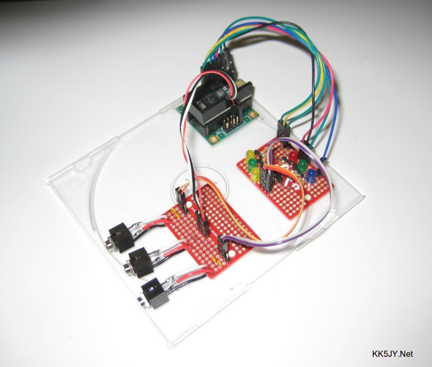
Modem Prototype Hardware
Figure 1: Prototype Hardware
for CW and RTTY
 
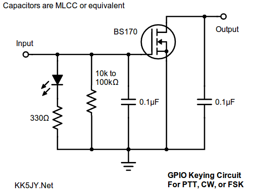
Keying Interface Schematic
Figure 2: Keying Interface Circuit
The hardware for these modems is fairly simple.  There are four small boards in the prototype:
The protype is shown in Figure 1.

Audio is read using the line in connection on the Teensy audio board.  The firmware can be configured for several different maximum audio levels, including typical line-level peak-to-peak voltages that are common with ham radio transceivers.

Since most modern radios have an FSK keying input, I chose to use the same hardware configuration for both version 2.0 modems.  The PTT function is the same for both modes, but the keying line is used for CW straight-key control, or for RTTY FSK shifting, depending on the firmware used.  The only difference is the cable used to connect to the radio.  An example keying interface is shown in Figure 2, based on the inexpensive and durable BS170 n-channel enhancement-mode FET.  Two such circuits can be added to a Teensy board to drive the PTT, FSK, and CW inputs of a radio, and the output pins selected can be configured in the firmware source code.

The audio codec could also support AFSK operation, and I may add that feature at a later time.  I prefer the hardware-keyed FSK and CW, so this arrangement is sufficient for now.

The firmware for CW and RTTY are separate for now, so changing modes requires changing firmware.  I bought two Teensy boards and two audio boards, so I'm covered for CW and RTTY. ;)  A future firmware release should be able to easily merge them into a single firmware image that can switch between CW and RTTY on the fly.  Such an arrangement might even have two dedicated keying outputs, one for RTTY and one for CW.


The Software

The modem devices are fully functional with nothing more than a simple serial terminal program to drive them.  This means that they can be operated from just about any modern device that has a screen, including Android, Rasberry Pi, or any tablet, notebook, or desktop computer.  The command interface is well-structured, so the modems can easily be integrated with a low-power embedded display device, if desired.

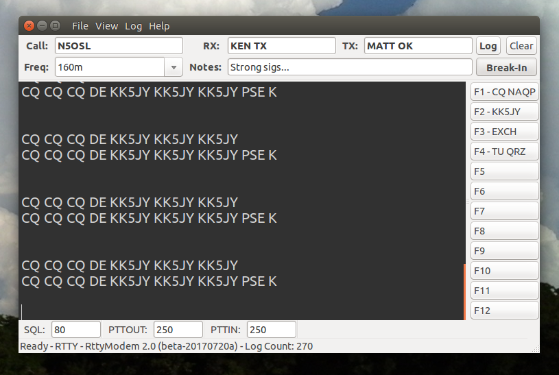
In order to use the modems in a contesting environment, however, a more complete user interface is needed, beyond a simple terminal or display.  To support this, I did a side-project called SMI Console, that uses the firmware's common modem interface for monitoring and changing settings.

The SMI Console software is shown in Figure 3, connected to the RTTY modem while it was decoding a recording of a noisy CQ call.  The UI software was written in C# using GTK+ as the UI toolkit, so the application can run on any Windows or Linux computer, including the Raspberry Pi and other SBCs.

SMI Console
Figure 3: SMI Console
The application supports basic logging, and a simple, efficient set of keyboard and mouse actions that can allow the contest operator to operate the radio and the log with a minimum of effort.  The result is a contesting interface that gives you everything needed to run or to S&P without removing your hands from the keyboard.  Intuitive mouse control is also provided, so that the most natural action preferred by the operator can be used for any given contesting task, whether that be copying received text into log fields, editing log fields, running and editing macros, or moving between the QSO and the log functions.

For example, there are shortcuts for all of the buttons on the screen.  So operating a macro button, adding a log entry, or toggling the break-in state can be done from the keyboard regardless of where the cursor is located.  Similarly, there is a shortcut for each of the text fields, including the QSO window, regardless of where the cursor is currently located.  There are shortcuts for selecting any of the settings at the bottom of the screen.  Pressing TAB cycles between the QSO window, the CALL box, and the RX exchange box.  When running in a contest, these are the fields that are accessed in succession.  You enter the call, and the exchange, and you often need to send something to the station, such as KA5? or AGN? or other such things.  No matter where you are in the workflow, you can get to where you need to be next in two TAB presses or less.  If you select text in the QSO window, either with the keyboard or the mouse, you can use keyboard shortcuts to place that text into any of the log text fields.

Macro buttons are placed at the right-hand side of the screen.  This is for several reasons.  First, most screens these days, including on embedded devices, are wide.  Placing the buttons vertically along the side, rather than horizontally, makes better use of the available space on the screen.  Next, traditional macro buttons appear horizontally to correspond to function keys on the PC keyboard.  However, this also places the button text horizontally, resulting in two different sets of boundaries between macros.  To scan the buttons with your eyes, you have to scan across the entire button text to get to the next button, and the amount of text in each button is different, which makes horizontal visual scanning awkward and slow.  Aligning the buttons into a column, where the text is all left-aligned, allows you to scan vertically for key text in a button, without having to scan across the text of all the buttons above it.  This is a subtle difference in workflow, but every little bit helps.

What is also important is what is not in the window.  There are no entry boxes for time-on or time-off.  These are computed automatically as you interact with the other fields.  There is no noisy waterfall ticking away on the screen.  In fact, the only tuning indicators are on the modem.  So when you want to center a station, you turn the radio knob and watch the modem indicators.  When the station is tuned, you go back to the keyboard.  This provides clean separation between functions, and it also eliminates the delay experienced by all waterfall displays due to soundcard buffering.  Supporting information such as operating frequency and log count are placed out of the way and in lighter font weights than the main fields.  The entire focus of the user interface is on the few tasks and fields that are used repeatedly as a contest progresses.

JayLog ADIF Editor
Figure 3: JayLog ADIF Editor
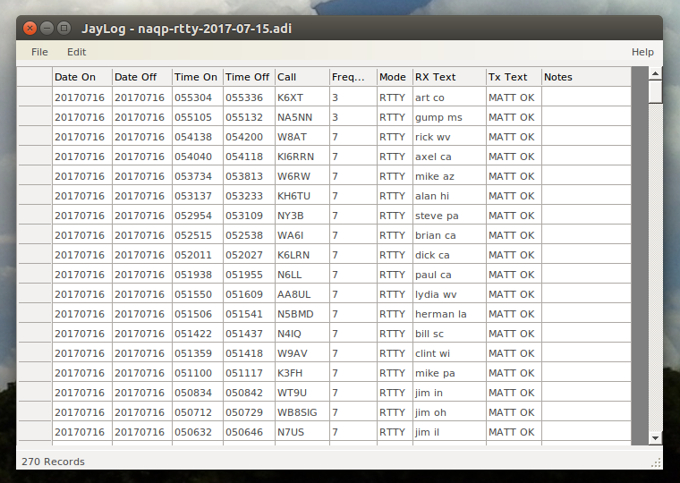
There is only one field for received exchange, and one for sent exchange.  It doesn't make sense to spend time during a contest run trying to pre-parse the various fields of an exchange.  The needed information can be captured in a single selection operation, and parsed later by appropriate ADIF software.  The log generated by SMI Console is ADIF, and all operations are done transactionally, so that the file can be used by SMI Console while it is being viewed in another application.  A minimal ADIF editing application was also part of this project, as shown in Figure 3.  Any ADIF editor can be used as long as it doesn't hold the active ADIF file open.

Both modems run in break-in mode.  When text is sent to the modem, it automatically asserts the PTT line and sends data.  When all data has been sent, and a short timeout occurs, the modem places the radio back into receive.  The SMI Console leverages this by using a single QSO window for both transmit and receive.  There is no explicit command to place the radio into transmit.  When you type characters, they are automatically transmitted.  When you stop typing, you are listening to the other station.  Macros are essentially automated typing -- when you click a macro button, the macro variables, if any, are expanded, and the resulting text is "pasted" into the QSO window, just as if you had typed it live.  At any point, the ESC button will immediately put the radio back into receive mode.  This allows CW operators to use a keyboard for full- or semi-break-in operation that is every bit as responsive as using a paddle and keyer.  Each modem supports configuration of the PTT lead-in and lead-out times, so the difference between full- and semi-break-in is achieved by setting the PTT timings to one's taste.  Alternatively, one can elect to simply omit the PTT connection altogether, which is common for CW operators who prefer full break-in (QSK) operation.

The result is a simple, tight, unified interface to contesting that can both encode and decode RTTY or CW using dedicated decoder hardware and firmware that runs in real time.  This means that the user interface device need not have any significant amount of CPU power at all, and the modem's DSP performance is independent of the UI used or the hardware on which it runs.  The SMI architecture is deliberately left open and modular, so that a modem might be connected to any number of terminal devices or software packages.

The workflow achieved using this combination of hardware, firmware, and software was the least demanding of any kind of computer-based contest interface that I have ever used, including HRD, FlDigi, or any of the logger/control programs.  Using software that focuses on the few essential contesting tasks, and allowing easy transition between those tasks, minimizes the operator workload.  Minimizing the contest workload results in a faster pace, fewer errors, and less stress on the operator.  The current software feature set is sufficiently complete that I will likely not use any of the monolithic software packages for contesting again.  The experience improvement was that good.


Firmware Details

Both CW and RTTY firmware use keying code that essentially unchanged from the original v1.0 modems.  The PTT and KEY outputs are driven by open-drain FETs.

The Teensy audio shield captures 16-bit stereo audio, at a 44.1kHz sampling rate.  The firmware passes the left channel only through a single IIR band-pass filter (BPF), the width of which is selectable.  In order to prevent ringing in the filter, a width of 500Hz was chosen by default.  This filter provides three different functions, all of which are important to optimal decoding of signals from the radio:
The output of the BPF is limited (clipped) so that all amplitude information is removed.  Users of FM are probably familiar of the concept of limiting used in FM analog radios.  This step is essentially the same in the modem firmware, and done for similar reasons.

This is where the two modems differ in their demodulation strategy:

The CW modem uses a PLL algorithm, which is similar to the LM567 tone decoder chip, but optimized for discrete-math operation in software.  The PLL settings have reasonable defaults, but can be adjusted by the user through the SMI interface, and the settings persisted in EEPROM.  The PLL uses boxcar integrators instead of the RC-style LPF used by the 567 and similar parts.  These are used to smoothe the I and Q detector outputs which drive the tone detection.  The I detector is used to drive the output state, while the Q detector is used to control the software VCO.

The blue LED is illuminated whenever there is CW tone present, allowing visual indication of the tone detection action.

The PLL Q-phase error level, similar to a loop control voltage in a hardware PLL, is separately integrated with an LPF, and then used to drive the tuning indicator.  The three tuning LEDs are lit to indicate the frequency of the received signal, with respect to the center frequency of the VCO.  If the signal is on-frequency, only the green LED is illuminated.  If the signal is slightly off-frequency, the green LED and one yellow LED will be illumuniated together.  If the signal is significantly off-frequency, only the yellow LED will illuminate.  One yellow LED is provided for each direction of possible frequency error.  This provides a quick visual tuning aid without requiring an elaborate waterfall or other such device.  Although the PLL jitter causes a small amount of display error at very low SNR, the indicator was reasonably accurate, and more than enough to ensure accurate decoding in a contest environment.  Even at low SNR, using the tuning indicator to zero beat another station will get you much closer to their frequency than most people bother to tune by ear.

The PLL approach allowed accurate detection of signals down to around -20dB SNR in wide-band AGWN.  This made the algorithm competitive with many of the popular software decoders in use, and was more than enough to serve as an extra set of ears as I worked CW stations.

In order to remain responsive, and with reasonable frequency accuracy, the PLL requires a sampling rate of at least 8kHz.  The default configuration in the firmware runs with 11.025kHz.

The RTTY modem uses a frequency discriminator that is driven by two very narrow resonant filters, each centered on one of the two expected FSK frequencies.  The output of each filter is individually rectified and run through individual low-pass filters, to measure the amount of signal within each of the filters.  These two levels are then continually compared with each other, to determine the net frequency deviation of an FSK signal that is reasonably zero-beat within the filters.  The frequency deviation is obtained by approximating the arctangent of the two signal levels as if they were X and Y coordinates on a unit circle.  Passing the resulting "angle" through an LPF and a simple hysteresis comparator provides the restored Baudot bit stream.

This approach is a bit brute-force, but when I compared it to the SNR performance of discriminators based on various forms of quadrature detector, the two-filter approach was superior by about 10dB, providing solid copy well below the -20dB SNR point in wide-band AGWN.  It did require a bit more adjustment to get the filter settings optimal, but in the end, it was able to copy truly weak RTTY signals in contest conditions.  I suspect the reason for its performance is the use of resonant filters, rather than band-pass filters, for each of the tone frequencies.  While no filter has zero width, the peaks of each of these filters has essentially zero width, making them ideal for frequency discrimination of individual tones.

The downside to using highly selective filters for detecting individual tones is that it becomes difficult to use any of the resulting information to drive a visual tuning indicator.  In essence, the signal is either aligned properly with the filters or it is not.  The amount of "offset" information available when the signal is off-frequency is quite limited.  What I was able to do was to use the error angle to drive the LED trigraph directly, so that the visual indication is that of the RTTY "diddle" on the yellow LEDs.  If the signal was within +/- 20Hz of zero beat, the yellow LEDs dance with the incoming tones.  If the signal drifts much beyond this, one LED will stop blinking, and with any further deviation, the other LED will stop blinnking.  The LED trigraph is essentially reflecting the hysteresis output, providing more of an alighment indicator than a large-offset tuning indicator.  As it turns out, this was good enough for contesting purposes, and it is accurate even at very low SNR.

Unlike with CW, FSK doesn't use key-up time as part of the signaling.  With CW, the empty space between key-down pulses is significant, and its length determines whether it is part of a letter, part of a word, or the space between words.  FSK uses 100% constant key-down to generate all of the signaling elements, with the two keying elements being the two different carriers.  This means that the RTTY demodulator can actually detect three distinct states from the received audio.  Since the discriminator output is independent of the signal strength, and depends only on the received frequency, the discriminator is either solidly left of center, right of center, or it is floating near the center.  This third state, where the deviation is near zero for an extended period of time is the output when there is no FSK signal present.  This allows the FSK demodulator to use a software squelch that operates properly even in the presence of fading, whether selective or full-signal.

The RTTY modem exploits this, and provides an optional squelch setting that will mute the received data stream if the discriminator spends a specific amount of time without achieving enough deviation.  The squelch operates with a configurable timeout and deviation limit, so that the details can be adjusted by the operator.  Since a single bit of sufficient deviation is enough to open the squelch, the de-squelch operation has essentially negative operating time, un-muting the received data stream before the initial byte from another station has completed transmission.  This avoids missing the initial characters of a transmission that arrive when the squelch is already closed.  The default settings allow the squelch to operate properly even with signals whose SNR is at the lower limit of the discriminator.

The most recent version of the firmware includes an algorithm for detecting selective fade, and providing some compensation for it.  The difference between the maximum tone amplitudes is taken over approximately one character time, and the imbalance is used to shift the mark/space threshold values.

The current software also runs a first-order lowpass filter over the recovered bitstream, to help minimize high-frequency transients when used on a noisy channel.

The handling of other tasks in the modems, such as T/R timing, command processing, etc., is quite similar between the modems.  Each firmware package has many options that can be configured, including center frequency, decimation divisor (which sets the sampling rate), the preselector filter width, and so on.  Many settings can be adjusted by the SMI Console as the modem runs, and the new settings are committed to EEPROM within the modem.  This allows for field calibration of those settings.


Firmware Command Sets

The firmware for both modes supports an extensive command set, that allows configuration of many operational parameters.  The format of the command interface is the same SMI protocol that was developed for the original CW modem, and is documented in more detail in that article.

The verison of SMI used in these devices has some additional features over the version explained in that article:

First, commands that accept a numeric value, or that accept one of a fixed number of available values (e.g., AUTO and MANUAL) also support special increment values of '+' and '-'.  These special values will cause the modem to use the next higher or next lower valid value available.  This can be used by user interfaces to support the idea of a 'knob' or 'spinner' that does not need to know the current value or range of valid values. The user can simply request that the value be turned up or down, via use of these special values.

Second, the DOC command will return a comma-separated list of valid commands.  In a future release, the DOC command will also support querying individual commands, to retrieve a description and range of valid values.

Current production command sets are described below:
Both modems support a number of commands, each of which has the same meaning regardless of the operating mode.  Some of these can be used by a user interface application to identify which modem is connected, and what commands are supported:
DOC
This returns the "doc string" which lists the commands that are supported by the modem.  In future revisions, the DOC string will support detailed query of individual commands, to better support fully-generic user interfaces.
VERSION
Query the version string of the firmware.
MODE
Query the operating mode of the modem.  This will return either CW or RTTY.
ECHO
Set or query terminal echo. ECHO=0 will disable echo of all data sent to the modem. ECHO=1 will enable echo of all bytes sent to the modem, whether commands or data. ECHO=2 will enable echo for transmit data only, and is intended for use when the modem is being driven by a dedicated application, rather than a simple terminal.  Echoing the data but not the commands simplifies the task of separating the data and command streams.
EC
Erases the EEPROM when set to a value of 1.  This is handy when reusing a board that already has EEPROM data stored in it.
DEV
Returns a smoothed and scaled value indicating the received signal offset from the center frequency of the modem.  The value returned is unitless, and possibly subject to scale and offset values configured with other commands.
PTTIN
Get or set the number of milliseconds between asserting PTT and starting to send transmit data.
PTTOUT
Get or set the number of milliseconds between the trailing edge of the last transmitted data element, and when PTT is released.
LEVEL
Returns the normalized audio level, in the range of 0 to 100.  This value is latched and resets each time this is called.  The value returned is the largest value encountered since the last LEVEL call, making this a 'peak' level query.
LINEIN
Get or set the volume level of the LINE IN channel of the codec's mixer.  Valid values are zero to 15, and each value corresponds to a specific peak-to-peak input voltage that will produce full scale readings from the A/D converter, these voltage levels are documented within the INO file.  Larger values produce more gain.  This setting should be adjusted to match the radio output to produce the largest LEVEL value that does not clip on strong signals.
DS
Returns the current state of the detector; the value is mode-dependent, and is mainly for debugging.
The CW modem also has a number of commands specific to CW operation.
RXWPM
Get or set the speed at which the decoder will expect to receive CW data.  If RXMODE is set to AUTO, this value can change between queries.
TXWPM
Get or set the speed at which the encoder will produce CW elements for transmission.
RXMODE
Enable or disable decoder speed auto-tracking.  Valid values are MANUAL or AUTO.
TXMODE
Enable or disable whether the encoder speed auto-tracks the receiver.  Valid values are MANUAL or AUTO.
CRLFBT
Enable or disable whether to convert BT prosign to CR/LF, or vice versa. 0 = disabled, 1 = enabled.  If enabled, this will cause the ENTER key on the keyboard to generate a BT prosign. It will also cause a received BT prosign to generate a CR/LF on the terminal.
DOT
Returns the decoder's current dot length, in milliseconds.
BOUNCE
Gets or sets the sampling interval of the software debounce filter for the CW input when an external hardware tone detector is used.

When using the LM567 emulation option (see above), there are a set of additional commands that can either adjust or query the operation of the decoder:
PLLOFF
Get or set the PLL reporting offset.  This is used to adjust the reported PLL offset so that a #DEV=0; is returned on a perfectly-centered tone.
PLLGAIN
Get or set the PLL reporting gain.  This is used to adjust the magnitude of the #DEV; for a given shift in frequency.  A larger value will cause #DEV; to return larger offset values.
PLLLOW
Get or set the PLL low-side asymmetry correction.  This applies a scale to the #DEV; reading when that reading is less than zero.  This corrects for assymetry in the PLL output either side of zero.
PLLI
Get or set the PLL in-phase integration window length.
PLLQ
Get or set the PLL in-quadrature integration window length.
PLLR
Get or set the PLL rail magnitude.
I
Returns the current in-phase average from the PLL.
Q
Returns the current in-quadrature average from the PLL.
The RTTY modem also has a number of commands specific to RTTY operation.
CSET
Get or set the character set to use; valid values include BAUDOT, ASCII7, and ASCII8.
UOS
Enable or disable unshift-on-space.
REV
Reverse the meaning of the two tones, for RX, TX, BOTH, or NONE.  This will reverse mark and space polarity in the decoder, and in the generated keying waveform.
TUNE
Key the transmitter with a constant carrier for tuning purposes.  1 to enable, and 0 to disable.
SQL
Squelch threshold, measured as a deviation level; set to zero to disable.
SQTO
Squelch timeout, in milliseconds.
HASH
Transmit a hash (#) character.  If a hash (#) character is received in the audio stream from the receiver, a #HASH; response will be sent to the host port unsolicited.  This allows the hash character to be passed in each direction without disturbing the command processing state.


Software Downloads

The firmware for the modems is available in source form, below.  Installation requires the Arduino software, and also the Teensyduino add-on to add support for the Teensy boards to the Arduino environment.

The SMI Console and JayLog software is also available in source form.  MSI installers will be available as soon as I can figure out how to package the GTK+ library installer within my own MSI.  These packages will build and run on either Windows or Linux; a Visual Studio SLN and a Linux Makefile are included in each source package for this purpose.

All software and firmware is released under the terms of the GPL version 3.  This keeps the products freely available to end-users, but also ensures that people who use this code in their own projects will re-release their improvements to the public.  This way, the amateur radio community will have access to any improvements that might go into any commercial product based on the software or firmware.

Modem 2.0 Downloads  (Click Here)

Click the link above to download firmware or software packages.  The source is being released under the GPL version 3, which is also available on the download page.

Note to Integrators: If you intend to use any portion of the source code in your own project, please make sure you are familiar with the terms of the GPL3 before you publish or release your product to the public.


Release History

2018-03-01 - Modem firmware update: include selective fading compensation, and bitstream LPF.
2017-11-10 - Modem firmware updates; bug fixes to SMI Console application.
2017-10-11 - Initial release of JayLog source.
2017-10-10 - Initial release of firmware and SMI Console source.
2017-07-25 - Initial article.

Links

Teensy - Open-source microcontroller and embedded development tools.
SparkFun - Supplier for Arduino boards and hardware.
AdaFruit - Another good source for Arduino hardware.

Copyright (C) 2017-2018 by Matt Roberts, All Rights Reserved.