CW Modem

Matt Roberts - matt-at-kk5jy-dot-net

Published: 2014-03-31

Updated: 2017-10-19


This article is for the original version, based on the Arduino Uno.  For the version 2.0 modem, based on the Teensy, see the Version 2.0 article.

Intro

Computer-aided CW (morse code) is one of my favorite activities.  I recently started playing with Aruduino boards for various ham applications, and thought a CW program for the Arduino might be fun.  This article describes hardware and firmware for encoding and decoding of on-air CW using an modem based on these controller boards.  This project has gone through several revisions, and now supports multiple interface options.  My original goal was just to get the Arduino to perform the morse code decoding operations, while offloading the tone detection to an external circuit.  I was surprised to learn that the little AVR microcontroller also has enough computing power to read audio data directly through its A/D converter, and then do some basic DSP detection and filtering of analog CW signals, without the need for an external tone detector.

I call this project a "modem," but it can be used with a simple terminal program for real-time keyboard-to-keyboard QSOs, or integrated into a more complex software package, as the command and configuration interface is readily adapted for use in existing programs.  From here in, I will refer to the "modem", but it is easily used as a terminal device by connecting to it using a terminal emulator such as miniterm or the Serial Monitor included in the Arduino development environment.  A low-power terminal option would be a Raspberry Pi running miniterm.

This project has also convinced me that the ham community is in need of adopting a standard modem interface for use with our more popular HF digital mode packages.  This would allow people to do exactly what I am describing here -- make new hardware-based controllers that will do the modulation and demodulation (i.e., the modem functions) without the need to modify the user interface.  But more on that later.

Hardware
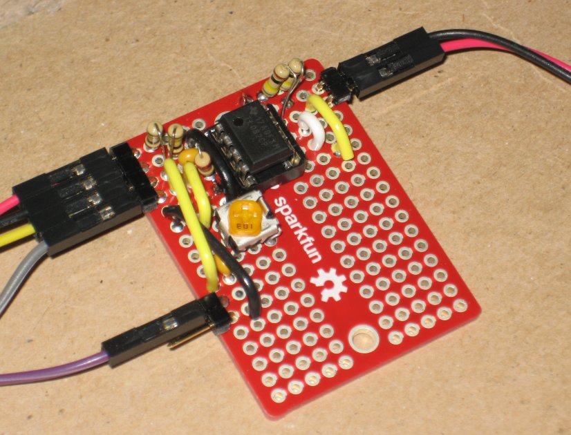
Figure 1: LM567 Prototype

The Hardware

The hardware I chose initially for the project controller consists of these essential elements:
Using the 567 decoder keeps the hardware interface simple, and uses logic-level signals for both transmitting and receiving.  Most of this article covers the 567 circuit, but the receiver can alternatively read audio tone data from the A0 pin of the UNO.  This option will be covered later in the article, because most of the firmware is the same between the two options.


The Firmware

The firmware consists of a simple program or "sketch" that does the timing and decoding functions.  It uses logic-level input and output pins to receive and send the CW pulses.  The choice of pins can be selected at the top of the sketch.

Two output pins are used to control sending.  One will control the PTT line of the radio, while the other controls the keying pulses.  Both should be wired to an n-channel FET or NPN BJT, so that the corresponding control lines are brought to ground when the output pin is brought high.  This is a very standard keying interface scheme.

For input, a similar circuit is used to detect CW pulses from the receiver. A digital input line is brought to ground whenever the CW tone exists in the receiver, and allowed to pull high at all other times.  This is the easy part.  In order to convert the tone into such a logical pulse, a decoder of is needed to detect the tone, described below.

The decoding logic within the firmware uses a moving average to track the WPM rate of arriving pulses.  Dots are shorter than the average, and dashes are longer. There is limiting logic in the firmware that prevents the moving average from collapsing in on itself whenever a long string of pulses are received that are of similar size.  E.g., if you send a string of dots, or a string of dashes, or if you are simply sending text with an excess of one or the other.  E.g., a callsign of "HI5HIS" received a few times would cause the moving average to collapse to the dot length.  Likewise, a call of "M0TOM" would collapse the average to the dash length.  The code has countermeasures to resist this tendency.


The Decoder Circuit

For this project, I chose the LM567 tone decoder IC.  This part is a rather old design, but it works well, and they are still quite common with several manufacturers offering pin-compatible parts.  I suspect the ongoing success of this part is that it implements an analog PLL circuit with the I & Q detectors and VCO built-in.  Such a device has all kinds of uses, even in modern circuit designs.  The 567 requires a very minimum part count, and operates from a humble 12mA of current at 5V supply, which is less current draw than many LEDs.  The circuit was originally marketed as a "tone decoder," but it can operate with a center frequency near 500kHz, which means that it is really a generic PLL circuit.  Looking at the data sheet, the circuit's specifications mean that it could be used as a complete CW, AM or FM receiver for RF signals below 500kHz, if desired.  In fact, some hams have used these devices for exactly this purpose.  Such designs yield synchronous receivers that can have very respectable performance.  Both the TI (LM567) and Philips (NE567) parts have a stated sensitivity of -6dB SNR in a 140kHz noise bandwidth, so the part should be an excellent choice for detecting a CW tone in a standard SSB channel.

The 567 is "programmed" through a handful of analog passive components, and its parameters include tone frequency and detection bandwidth.  Example circuits are all over the internet, but the main item of interest here is that the output of the LM567 (on the 8-pin DIP package, this is pin #8) is brought to an input pin on the controller, so that the receive data can be read.

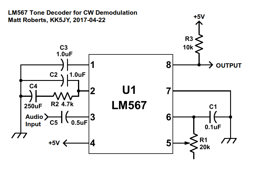
Figure 2 - Example 567 Schematic
(Click to Enlarge)
Figure 2 shows an example schematic for the 567 chip.  This is a modified example from an old data sheet.  Values used for my first prototype detector board are as follows:

R1: 10kΩ to 20kΩ trimmer, to adjust the center frequency, f0.
R2: 4.7kΩ
R3: 10kΩ to 100kΩ; this is a pull-high resistor for the open-collector output.
C1: 0.1μF
C2: 1.0μF
C3: 1.0μF to 2.2μF; see below.
C4: 250μF

The 13k trimmer, R1, can be sized to provide whatever frequency range is desired.  At around 9kΩ, the center frequency is 1kHz.  At 13kΩ, the frequency is 700Hz.  A 20k trimmer would extend the lower frequency range to below 400Hz.  To restrict the tuning range to a smaller value, you can use a fixed resistor in series with a trimmer.  E.g., a 10kΩ fixed resistor in series with a 10kΩ trimmer will produce a frequency range between roughly 450Hz and 950Hz, which is close to the typical range used for conversational CW.  Trimmers and fixed resistors are readily available in these sizes.  The tuning speed of the trimmer when used in such a fixed-trimmer pair is determined by the ratio of the fixed value resistor to the maximum trimmer value.

The 1μF capacitor, C2, is used to control the detection bandwidth.  That value gives approximately 10% to 15% bandwidth when the f0 is between 400Hz and 1000Hz, which corresponds to a bandwidth of approximately 70Hz to 100Hz, respectively.  This is fairly narrow, and should give good selectivity.  To increase the detection bandwidth, use a smaller value for C2; to decrease the bandwidth, use a larger value for C2.

These values provided a reasonable bandwidth and sufficient responsiveness for machine-sent CW up to about 30WPM.  Above this, the 2.2μF output filter is a little too large, and the state transitions aren't prompt enough for reliable copy.  Dropping the value of C3 to 1.0μF allowed for good copy up to about 50WPM on my board.  According to the data sheet, the value of C3 should be at least twice the value of C2, but it doesn't explain why.  I suspect the reason is that a ratio of 2:1 provides a good match between PLL loop responsiveness and output responsiveness.  In any case, it is clear that the with careful adjustment of the values, the circuit can be made to work with a wide range of transmission speeds.

That said, it is worthwhile to note that the 567 chip does have a switching speed limit that is determined by the center frequency.  According to the data sheet, the fastest on-off cycle rate is determined by f0 / 20.  What this means in practice is that lower center frequencies will yield lower maximum WPM decoding rates.  By my calculations, a center frequency f0 of 400Hz will have a maximum decoding limit of 24WPM, a center frequency of 600Hz will have a limit of 36WPM, and a center frequency of 800Hz will have a limit of 48WPM.  Whether this is an issue depends on your operating preferences.  I tend to run my decoders at 700Hz, which is most comfortable to my ears, and at that f0 value, the maximum decoded rate is 42WPM, which is fine for me, even under my most aggressive contest days.

One challenge that I ran into early on with this board was VCO stability.  I found two different causes for this, and both are easily corrected with careful circuit design.  First, the value of R1 must be stable for the VCO frequency to be stable.  This seems very obvious, but I found that many potentiometers were a bit on the "cheap" side, and their values tended to drift for any number of reasons.  One in particular would drift substantially if the board was gently bumped.  So selecting a good-quality potentiometer is a must for reliable operation of the 567.  The second challenge had to do with voltage stability at the 567 chip.  The +5V output from the Arduino can be a little noisy, and this can cause substantial jitter in the 567's VCO.  This only makes sense, since a VCO is a voltage-controlled oscillator.  By placing a small capacitor, 4.7μF, connected between pin 4 and pin 7, right at the chip, the voltage for the 567 was stabilized immensely.  This is a well-known best-practice with such designs, and it definitely helped here.


Operation

Operating the unit is straightforward.  Just connect to the controller through a serial terminal program or the serial monitor in the Arduino environment.  When you type characters, the transmitter is enabled, and the keying line will send the text you type.  When you are done typing, the radio will automatically go back into receive mode after a short delay, and the decoder will attempt to decode incoming CW characters.  This is very VOX-like operation.  For those who are familiar with CW operation, the behavior is semi-QSK when using the PTT line, and can be full-QSK if the PTT line is omitted and if the radio supports full QSK T/R speeds.

The command interface is documented below, and commands can be sent inline with the text.  When a proper #command; sequence is sent, the modem will respond appropriately.  E.g., sending #RXWPM; might return a response of #OK:RXWPM=25;.  If a bad command is typed, e.g., #DOG;, the modem returns #ERR:DOG;.  Any characters sent to the controller outside of the "hash-semicolon" wrapper are interpreted as text to send.  Characters sent from the controller to the PC outside of the wrapper should be treated as received text from the decoder.


First Impressions

The firmware sends CW flawlessly.  To test with a real radio, I used a couple of 2N2222 transistors, one for PTT and one for the key output.  When testing with an HF radio, sending timing was excellent.

The reception also works flawlessly when connected directly to a K1EL keyer that produces flawless CW pulses.  When the decoder board is used, and connected to the audio output of a PC running FlDigi, the decoder seems to produce results that are similarly accurate.  If the speed of the received code is changed abruptly, the automatic speed tracking appears to be able to immediately recover if the new speed is within about 10WPM.  It recovers quickly if the WPM excursion is larger.  The window length of the moving average used to track the received pulses can be adjusted in the code.

When testing with the 567 circuit, I found that the VCO of the LM567 is understandably sensitive to the cleanliness of the power supply voltage.  As a result, I had to add a filter capacitor to the power supply leads of the chip on the 567 breadboard in order to keep the VCO stable and on-frequency.  The controller's variable computational load can cause some fluctionations in the power supply voltage that must be removed by such a filter.

I'm still tinkering with on-air testing, but the first attempts are promising.  When listening to 40m ragchews, the firmware handles decoding timing a little better than fldigi.  On the other hand, the 567 requires more drive than fldigi for best decoding.  The data sheet says that 200mV peak-to-peak is optimal, so depending on the receiver output level provided by the radio, it may be necessary to provide either an op-amp preamplifier or some attenuation for best results.

For those looking for a more recent decoder design than the LM567, there is an FSK part from JRC, part number NJM2211.  The cost per unit is more than double that of the LM567, but it does have some nice features, including an even lower power consumption than the 567.  This part supports tone decoding, FSK, and even FM demodulation, which makes it useful for CW, RTTY, MFSK, or analog modes like maritime weather fax.  I used a board based on this part for RTTY decoding in the RTTY modem project.


Why We Need a Standardized Modem Interface

While working on this project, I realized that the best way to test out the software is to work a contest.  Unfortunately, all of the contest-ready packages only support built-in modes.  It occurred to me that if we could add just one more "mode" to each of these packages, we could, from that one mode, support all kinds of hardware and software interfaces for all kinds of modes.  The only missing piece that is needed is an interface that supports some key components:
  1. Text decoded from the receiver.
  2. Text to be encoded and sent to the transmitter.
  3. Commands and Configuration.  E.g., Transmit, Receive, Set WPM, Read WPM, Set BPS, etc.
This modem firmware provides such an interface.  The first two items are the default data streams sent to/from the device on the serial port.  By default, all bytes are either encode or decode bytes.

The third item is implemented by special packets encoded in the data stream.  The general form is #key; for simple requests, and #key=value; for requests that require one or more values.  When the modem device encounters these in the outgoing transmit stream, it removes them before encoding is done, and they are treated specially.  The responses are interleaved into the receive data stream, and removed by the user interface software.  Responses indicating success have the key prepended with OK: while an ERR: prefix is added to failed requests, as described in the examples above.  Such a scheme is easily coded into an existing application, but it can also be decoded easily by a human just watching the byte stream go by on a simple serial terminal.

The pound or hash sign indicates the start of the request, and the semicolon terminates it.  If a hash or semicolon is needed inside the command, any part of the command sequence can be escaped with quotation marks.  If the hash is needed in the data, the special sequence of #hash; can be sent in either direction.  Note that the semicolon does not need to be escaped in the data stream, because it only has special meaning when prefixed by a hash.

The current CW firmware provides several command and configuration messages: This kind of simple interface, if added as a generic Modem mode to packages such as HRD or FlDigi, would allow limitless experimenting with new modes and new modulation techniques, without having to change the software package itself.  These packages already allow the assignment of buttons and sliders to various radio-specific controls and settings.  Such items could be assigned to the kinds of key-value pairs described above.

The "Modem mode" should provide both serial devices and TCP sockets, allowing a network interface to be used in lieu of a serial port.  That would allow, for example, a modem application running on one computer to talk to FlDigi running on another. It would also allow modem appliances to use network interfaces (e.g., ethernet or wi-fi) instead of serial or USB connections.


Hardware
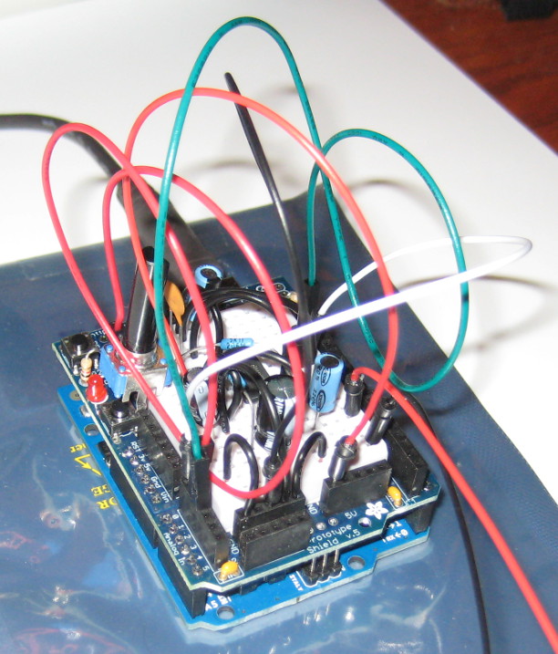
Figure 3: Audio Buffer
Software Tone Detection

The CW decoder firmware operates on binary logic signals, which are either on or off.  It will operate properly regardless of the source of the detected logic pulses.  When properly configured, the AVR microcontroller on an Arduino can also read CW audio frequency tones from its A0 pin, without the need for a hardware tone decoder.  The only hardware required is a buffer amplifier that can raise and offset the signal level to the 0V to 5V measurement range of the Arduino A/D (0V to 3.3V for 3V boards).  Such an amplifier circuit is discussed in more detail in the RTTY modem article, and the hardware interface used is identical to the one shown in that project (shown in Figure 3).  The sketch itself only requires a few minor configuration changes, which are documented in the CwModem.ino code file.  The firmware then uses some basic DSP techniques to detect the on-off keying of the received CW stream.

The software tone detector uses a delay line to multiply the incoming signal by itself, delayed by one wavelength at the desired CW audio frequency.  This is then run through an integrator to generate an envelope value that represents the amplitude of the audio at that frequency.  This is then run through some dynamic threshold and hysteresis logic to convert the constantly varying envelope value into a stream of logic on and off values, which look nearly identical to the output waveform from an equivalently configured 567 circuit.  Since the 567 generates inverted output voltage through its open-collector output, the polarity is inverted when using a hardware demodulator, but the signals are otherwise the same.  The firmware will handle either case, depending on which demodulator type is used.

I was very surprised to discover just how much work can be done by the Arduino's processor, which is an ATMega-328.  At the standard UNO speed of 16MHz, the Arduino has proven to me that it is capable of implementing any digital mode that amateur radio can throw at it.  This is truly QRP computing.


Software Downloads

The current version of the software is available for download.  The firmware is only available in source form, and can be read and uploaded to an Arduino by the Arduino Software.

CwModem Downloads  (Click Here)

The source is being released under the GPL version 3, which is also available on the download page.

2016-10-28 - Added AF DSP tone detection as a firmware option.

2016-07-28 - Added an example decoder schematic to the website article.

2014-04-11 - This version uses a lot less RAM than the previous version, making room for more features.  It has also been tested on the Arduino Mega 2560 board.

2014-03-31 - Initial release.

Links

Arduino - Open-source hardware and embedded development tools.
SparkFun - Supplier for Arduino boards and hardware.
AdaFruit - Another good source for Arduino hardware.

Copyright (C) 2014-2017 by Matt Roberts, All Rights Reserved.