Phased Array of Dipole-on-Ground Antennas for HF Reception
Matt Roberts - matt-at-kk5jy-dot-net
Published: 2016-04-29
Updated: 2018-07-09
Close-spaced phased arrays exhibit useful directivity characteristics for reception
of skywave signals. The dipole antenna is a natural and simple element type
for a phased array antenna, and the placement of untuned (nonresonant) horizontal
antenna elements very close to the ground provides a pattern that is a useful
building block for constructing such arrays. Combining the concepts developed
in the loop-on-ground with those from the
small loop array, and substituting a nonresonant
dipole for each array element, another type of space-efficient phased array can be
realized. This array has a far-field pattern that is very similar to that of
the array of small vertical loop antennas, combined with the space-efficiency and
stealth of the Loop-on-Ground.
The loop-on-ground is not the only form factor for a ground-mounted horizontal
antenna. A simple dipole has a nearly identical pattern when mounted on the
surface (is a dipole-on-ground a DoG?), and realizes a different kind of space
efficiency. The dipole-on-ground yields a similar electrical efficiency
(peak gain) as a square loop when each leg of the dipole has the same length as
each side of the loop. This means that the dipole's space distribution
trades length for width. That is, a dipole is a thin line across the ground,
but it is twice as long as any side of a square loop, and offers similar electrical
performance.
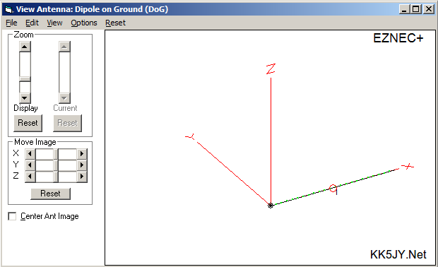
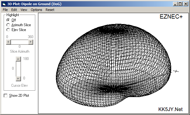
Figure 1 shows the EZNEC+ model and three-dimensional pattern of a single
dipole-on-ground element.
Figure 1: EZ-NEC Antenna Model and 3D Pattern for a Single Element
The main lobes of the dipole are off the ends of the wire, particularly at low
elevation angles. The pattern is very similar to the LoG
antenna pattern, or that of an electrically small vertical loop, mounted
substantially less than λ / 4 above the ground. Like any
of those antennas, the pattern is vertically polarized. Like
the LoG, the elevation-plane gain in the main lobe is nearly uniform
across all elevation angles, allowing the antenna to hear both high-angle
(NVIS)
and low-angle (DX) signals.
Note that the dipole-on-ground is not a "low dipole", such as those
mounted a few feet above the ground and used as an NVIS transmitting antenna.
Just as with the LoG antenna, this antenna element is deliberately mounted
on the surface, which cancels the horizontal response of the antenna
pattern.
The single dipole element, mounted on the ground, can by itself be an effective
receive antenna, just like the ground-mounted loop. If significant directivity
is not needed or desired, the ground-mounted element can still offer an improvement
in received SNR over typical transmit antennas, especially on the longer wavelengths.
The installation considerations are also very similar to the loop-on-ground, and the
two antenna types can be interchanged with similar results.
The remainder of this article describes a phased array of ground-mounted dipole
antennas, very similar to the phased array of vertical loop antennas. In
fact, most of the material in that article related
to feedlines and phasing is also applicable with DoG elements, so it will not be
repeated here.
In order to use the dipole-on-ground in a phased array to obtain a unidirectional
azimuth pattern, the elements are positioned end-to-end, in a straight line.
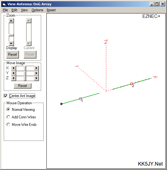
Figure 2 is an EZ-NEC model of a
two-element endfire dipole-on-ground. The elements are each 180 inches
long (15ft), with 60 inches (5ft) of separation between the elements at their
closest point. The overall length of the antenna is 35'.
Figure 2: EZ-NEC Antenna Model End-fire Array
As with the vertical loop array, the dipole array
requires preamplifiers to isolate the antenna from the delay lines. Otherwise,
the asymmetric reflections within the delay lines will spoil the front/back ratio
of the pattern. Alternatively, the individual elements can be loaded with
resistance to match them to the feedlines, but doing so decreases the element gain
significantly, which causes even more preamplifier gain to be needed. So the
simplest solution is to use equal feedline lengths between the untuned, unloaded
elements and the preamplifiers, and then place the delay lines between the
preamplifiers and the combiner.
When properly phased, the array can produce a pattern similar to the array of
small vertical loops:
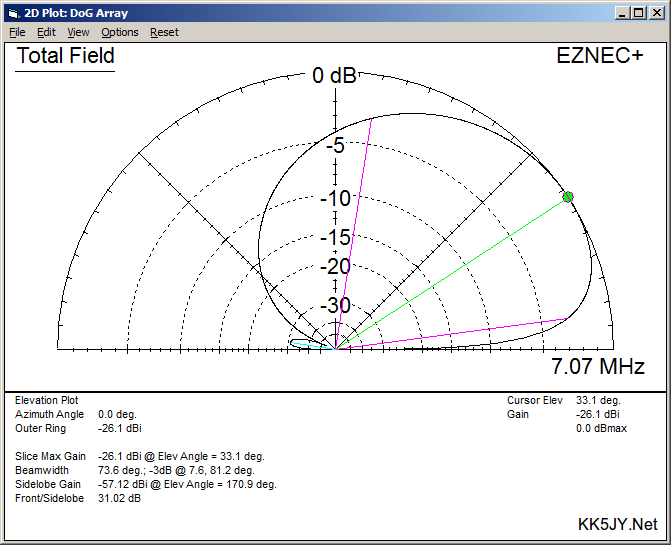
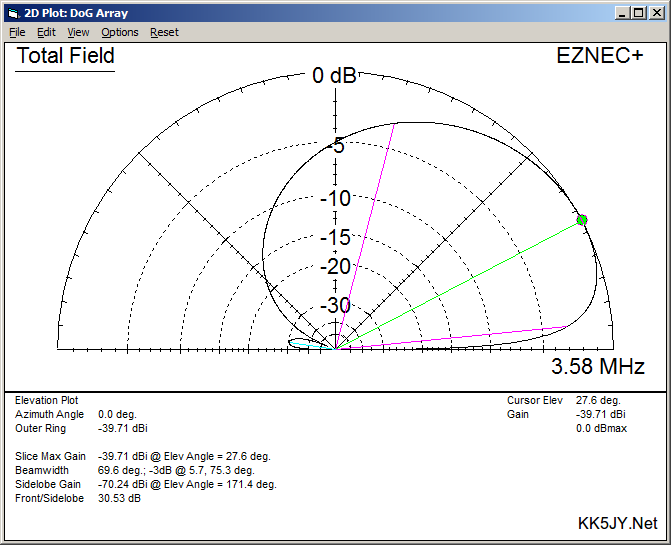
Figure 3: 40m Elevation Plane
Figure 4: 80m Elevation Plane
Figure 5: 160m Elevation Plane
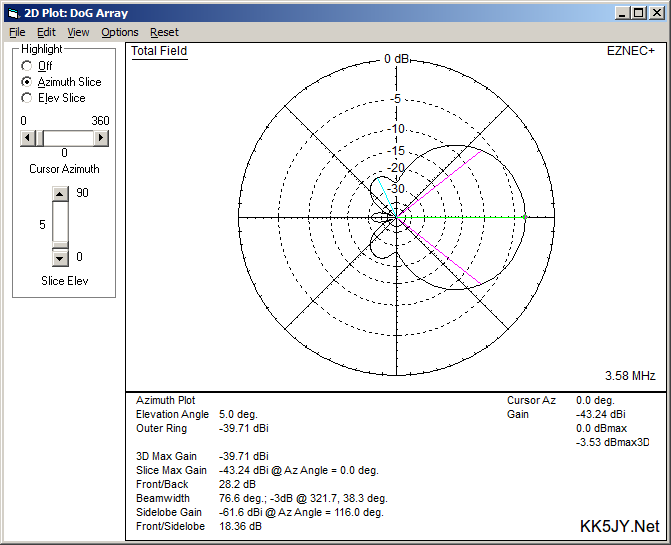
The azimuth profile of this antnena is essentially the same as with the vertical
loop array. Azimuth plots are shown here for 80m response, at the elevation
of peak response (~27°) and at 10° elevation.
Figure 6: 80m Azimuth Plane 27° Elevation
Figure 7: 80m Azimuth Plane 10° Elevation
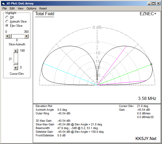
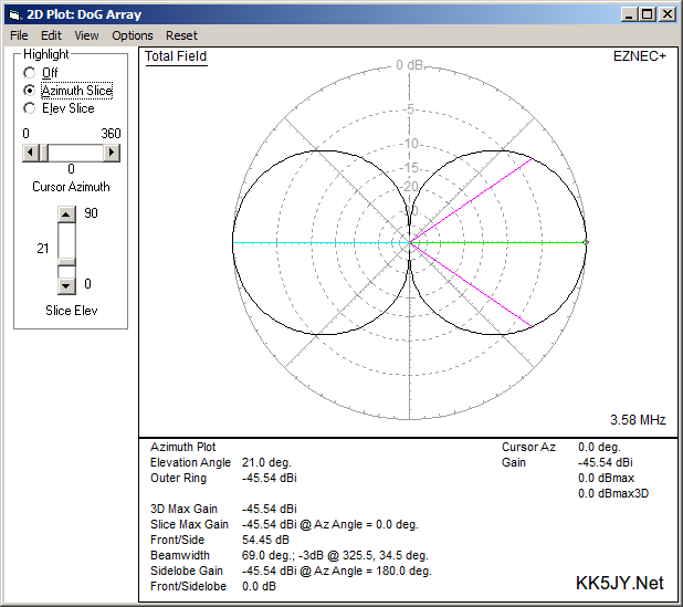
The shape of the azimuth pattern is similar down practically to the horizon.
This is the predicted azimuth at 5°:
Figure 8: 80m Azimuth Plane 5° Elevation
The delay lines used in the model for 40m and 80m are 133° and 156°,
respectively. As with the vertical loop array, the required delay is
dependent upon the size of the elements, and the spacing between them.
The main feature distinguishing this design from the
vertical loop array is its physical profile.
The long, thin profile of this antenna makes it ideal for installation almost
anywhere. The centerline of the antenna "points" in the direction
of the main lobe, and the antenna direction can be electrically reversed by
swapping the delay lines on the receiver side of the preamplifiers. This
makes aiming the antenna much easier than an array built from the loop-on-ground
elements. Otherwise, this antenna behaves similarly to the vertical loop
array.
In fact, it should be trivial to construct an array like this with a spacing
rope between the two elements to ensure a predictable gap between them as the
array is moved. This rope and the two elements could be tied together so
that they are one continuous line, which would make installation or relocation
trivially easy. A temporary or portable version could be held to the ground
by just two tent stakes, one at each end of such an assembly, and the spacing
would be guaranteed as long as the array was pulled tight before staking it to
the ground. This is a significant improvement over the LoG, which
requires some care during layout, to maintain loop symmetry.
The calculated
RDF
for 40m and 80m is also similar to the vertical loop array, with values of
8.9dB and 9.2dB, respectively. This places it on par with
a well-designed and constructed Beverage
antenna that is several hundred feet long, yet this model fits in a space
that is only 35' long.
A Note on Spacing
The spacing between the elements doesn't appear to be critical to producing a
predictable pattern. In fact, the important measure is the distance
between the current maxima of the two elements — that is, between the two
feedpoints. The examples in this article assume a gap of several feet between
the opposing ends of the elements, but this is not necessary. As long as the
two ends are not touching, the array can produce the patterns shown above with
appropriate phasing. So spacing distances from several feet down to a few
inches are all appropriate for this type of phased array. This can be
helpful if you are trying to squeeze an array into a small space.
The Antiphase Array
Another arrangement that can be accomplished with the array of two identical
elements described above is an antiphase array. This design places the
antennas 180° from each other electrically. Instead of using a delay
line to achieve a specific angle, an antiphase array can use identical feedlines
to place the two elements at opposite polarities from one another. This
is accomplished by reversing the wiring of one element when connected to the
feedline or isolation transformer. This also eliminates the need for
buffer amplifiers that are required to prevent reflections with other phase
angles.
The antiphase array produces a very unique pattern, that is quite different
from the single element and the phased array patterns shown above. First,
the antiphase array has a broad null overhead, suppressing NVIS signals.
Second, the antiphase array produces two main lobes, in opposite directions,
with the centerlines colinear with the array elements. The two lobes are
slightly narrow in the azimuth plane, and much narrower in the elevation plane,
than the other arrangements of the dipole-on-ground.
For example, here is the antiphase array using the same elements as the antennas
described above, on 80m:
Figure 9: 80m Antiphase Array Elevation Plane
Figure 10: 80m Antiphase Array Azimuth Plane
As you can see, the elevation plane shape in the direction of the main lobes is
very similar to that of a vertical antenna — large null overhead, and maximum
reception gain at low angles. However, the azimuth plane pattern shows two
deep nulls broadside to the antenna elements, with a reduced 3dB beamwidth in the
main lobes, and a near-perfect figure-eight pattern. This makes the azimuth
plane response much more like an STL or a classic dipole antenna. This gives
the antenna the directivity advantages of both a vertical and an STL, with a very
nice "arc-shaped" null from horizon to horizon, broadside to the array.
For people who want to improve their DX reception, and are looking for a design
that gives them bidirectional coverage (such as in the US, where most distant
stations are located to the east and west), the antiphase arrangement can provide
a pattern that is very competitive with an unterminated beverage. For example,
the RDF of the 80m antiphase example shown above is 8.6dB, making it quite
competitive with an unterminated Beverage antenna, but with better elevation angle
performance from a much shorter length of wire. The antiphase design has the
added advantage that a simple
passive combiner
should be all that is needed to produce a reliable pattern.
More to come...
Copyright (C) 2016-2018 by Matt Roberts, All Rights Reserved.