
Small Loop Antenna Array for HF Reception
Matt Roberts - matt-at-kk5jy-dot-net
Published: 2016-03-24
Updated: 2018-12-15
While working with small transmitting loop antennas, I noticed that there has been
considerable discussion (and disagreement) regarding
receive-only loop antennas, and
low-gain receive antennas in general. The same inductive
feed loops used in transmitting loop antennas are sometimes used in larger sizes, in isolation, as receiving
loops. This seems to be most common for
direction-finding applications, but also for
dedicated receive antennas on lower frequencies, such as 160m or 80m. Nonresonant, lossy loop antennas
have some nice response characteristics that make them ideal when used for reception of skywave signals, and
some very successful high-performance receive loops are now being offered as commercial products.
There has been considerable study into the use of phased arrays of nonresonant vertical antennas for
reception of long wavelengths. Antennas such as the four-square and two-element end-fire arrays have
all been used with short, lossy vertical elements, to provide highly-directional, low-noise receive antennas
for the lower HF and MF bands. The Beverage antenna—another vertically-polarized receiving antenna—has
also been used in broadside arrays to provide similar performance where space for such devices is available.
While doing EZ-NEC design for a two-element array over vertical monopoles,
I decided to substitute a small, vertically-polarized loop element in place of the
vertical element. As it turns out, this substitution provides significant benefits over an array of
vertical whip antennas with the same spacing. Both antennas can be made broadband by keeping the elements
reactive and lossy, but the loops have additional benefits:
- The elements are self-contained, and do not require radials.
- The resulting pattern has a ~50% narrower azimuth-plane beamwidth.
- Small, directly-fed loops are DC-shorted feedpoint antennas, with associated immunity to static buildup
and lightning-induced energy pulses.
The first point above is mostly mechanical. It minimizes the real-estate
needed for an array of any spacing. It also reduces the ground dependence
of the antenna in the near field. The second point is more interesting,
because it allows a two-element array of loops to provide a much more focused
pattern than the same array would when using vertical elements. The
predicted beamwidth is on par with a one- or two-element beverage antenna many
times longer than the loop array spacing. This enables very small arrays
to be extremely effective even for long wavelengths.
The rest of this article describes a directional antenna formed from a pair
of such loop elements. For a discussion of using a single small loop
element for HF reception, there is a seperate article
on that subject.
For the plots below, the following construction is used:
- Each element is a diamond-shaped loop, fed at the bottom corner, with 30-inch sides (10-foot circumference).
- The loop elements are placed approximately one diagonal loop diameter above the ground.
- The loop elements are aligned such that they are coplanar.
- The loop spacing is twenty (20) feet, measured between the loop vertical center axis; in other words,
the distance between the supporting masts.
- The elements themselvs should be carefully decoupled from the coaxial cable feeding them. This
can beat accomplished using a high-quality coaxial choke, or an isolation transformer such as is
commonly used for Beverage antennas. This helps preserve the loop pattern by preventing
current from flowing on the outside of the coaxial cable shield.
- Each element has a mast-mounted preamplifier, and the feedline length between the preamplifier and the loop
feedpoint is equal for both elements.
- The phasing delay between the two elements is provided by feedlines of differing lengths.
- The receiver-facing end of the delay lines are tied together using a passive signal combiner.
The preamplifier is a critical component, not so much for recovering sufficient signal levels, but to isolate the antenna
from the delay lines. The delay lines cannot be allowed to run with any significant SWR, because doing so causes wave
interference effects that destroy the pattern of the antenna. Tests with single 30" loop elements
show that these elements collect more than enough signal to set the noise floor in any decent receiver on 40m and 80m in a suburban
environment. So unless then antennas are located in a very quiet rural area, a unity-gain amplifier would be more than sufficient
to isolate the antenna from the delay lines.
The EZ-NEC model of the loop pair is shown in Figure 1. The main lobe of the
antenna pattern projects in the direction of the positive X axis.
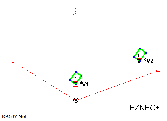
Figure 1: EZ-NEC 3D Wire Model
Plots are given for five different wavelengths. For each wavelength three different plots are given:
- Elevation, at azimuth of peak gain
- Azimuth, at 15 degrees of elevation
- Azimuth, at elevation of peak gain
Each plot is computed with the antenna above fairly good ground (0.0303S/m, and a dielectric constant of 20).
The phase delay between the elements is adjusted for best low-angle front-to-back ratio for each band. The performance
for each band is remarkably similar. Note that overhead response is considerable for all of the bands that support
NVIS. This allows for use of the antenna
for communications both at DX angles and within the skip zone.
The bands plotted, associated optimal delay line lengths, and the matching physical delay line length for
Belden 8241 are given by:
- 20m - 90° - 11.5'
- 30m - 115° - 20.5'
- 40m - 135° - 34.5'
- 80m - 157° - 79.1'
- 160m - 168° - 164.9'
Other cable types will require recalculating the desired delay using the velocity factor of that cable.
Note that any length of delay line can be used between the preamplifiers and the combiner or mixer; the critical component
is the difference between the length of the lines between the preamplifiers and the combiner. For lines that
are too short for the 20' spacing, simply add the needed length to both cables, which will give the same effect.
There are other ways to accomplish this with shorter lines, but this is the most straightforward, and is only an issue with
lines that are already short, such as the 20m example above. Depending on the installation details, another option is
to add 360° of cable to one of the delay lines, if this makes more sense mechanically.
The delay line length becomes particularly critical as the wavelength increases, because the 20' spacing is a progressively
smaller fraction of one wavelength. That said, constructing an accurate delay line with the needed resolution is just
as easy with long wavelengths, because each degree of length is larger at longer wavelengths. Longer wavelengths also
require longer delay lines, with 160m requiring more than 160' of length differential between the feedlines. Compensating
for this is the fact that good quality 75-ohm cable has very small loss at such low frequencies.
The azimuth-plane beamwidth is consistently close to 90°, especially at the lower angles, and regardless of band.
This is possible because the loop antennas each have nulls to the side, whereas vertical monopole elements have a single null
overhead. The side-facing nulls help to "squeeze" the overall pattern to provide much better directivity than
with an equivalent array of monopoles.
Example elevation plots are shown below. Note that the so-called "take-off angle", or angle of maximum response,
is lower for longer wavelengths. More importantly, the lower -3dB angle also drops for the lower bands, giving strong
response at the low DX angles, well into the single digits.

Figure 2: 20m Elevation Plane
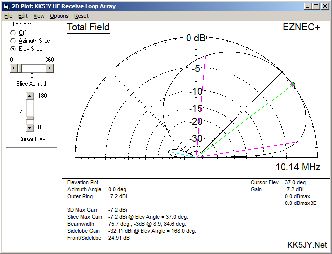
Figure 3: 30m Elevation Plane

Figure 4: 40m Elevation Plane
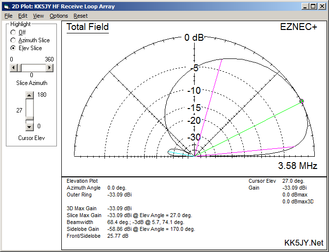
Figure 5: 80m Elevation Plane

Figure 6: 160m Elevation Plane
The magnitude of the rearward-facing minor lobe is a function of the magnitude of the delay. By making small adjustments
to the delay, the minor lobe can be made even smaller than shown here. The trade-off is in the rearward-facing higher-angle
response of the antenna. The delay lines shown here were selected so that the 180° response was roughly the same magnitude
as the two quartering sidelobes at low angles.
Here are the azimuth plots for the 15° elevation plane. Note that the 3dB azimuth beamwidth is close to 90 degrees on all
bands, and even less on the lower bands. As a result, the antenna has excellent directivity for DX work, regardless of the wavelength.
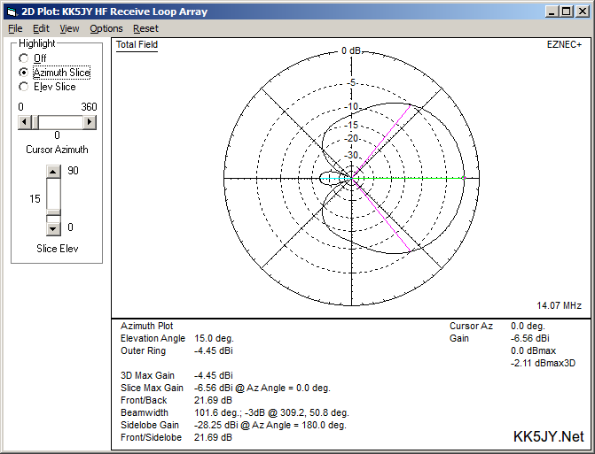
Figure 7: 20m Azimuth Plane (15° elevation)

Figure 8: 30m Azimuth Plane (15° elevation)

Figure 9: 40m Azimuth Plane (15° elevation)
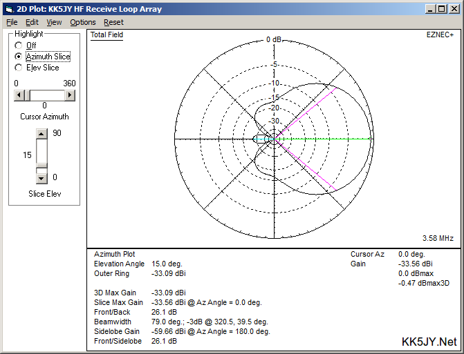
Figure 10: 80m Azimuth Plane (15° elevation)
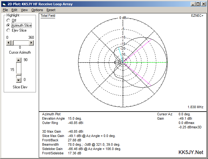
Figure 11: 160m Azimuth Plane (15° elevation)
For comparison, here is the azimuth plane at the elevation angle of maximum response. The shorter wavelengths have wider
bandwidths in this plane, because the plane is at a relatively high angle. Compare this to the azimuth plots at 15°
elevation. At the lower elevations, the directivity remains intact, even on 20m. This directivity is important for
noise and interference rejection.
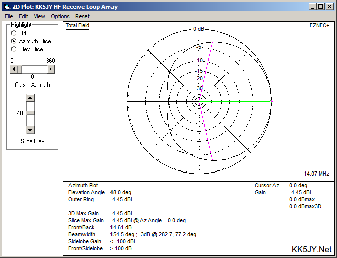
Figure 12: 20m Azimuth Plane (Peak Elevation Angle)

Figure 13: 30m Azimuth Plane (Peak Elevation Angle)
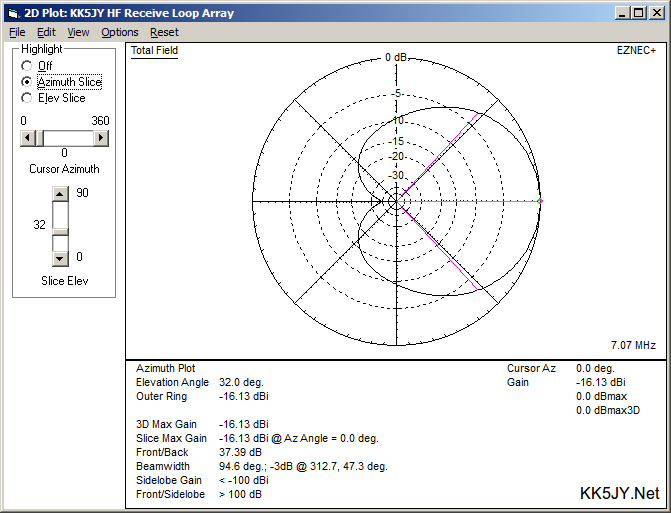
Figure 14: 40m Azimuth Plane (Peak Elevation Angle)

Figure 15: 80m Azimuth Plane (Peak Elevation Angle)

Figure 16: 160m Azimuth Plane (Peak Elevation Angle)
The azimuth response on shorter wavelengths can be narrowed by moving the antenna elements closer together. The azimuth response
is partly a function of the element spacing as measured in wavelengths. On 160m, the 20' spacing is less than 4% of one wavelength,
while on 20m, the 20' spacing is more than a quarter wavelength. A 10' spacing on 20m would narrow the azimuth response by several
degrees. The plots shown above assume a constant 20' spacing, where only the delay lines are changed in order to change bands.
The resulting responses, while excellent, are somewhat of a compromise between good element spacing and delay line criticality across
the four bands of interest. Again, the focus of the 20' spacing is to optimize pattern shape for the longer wavelengths.
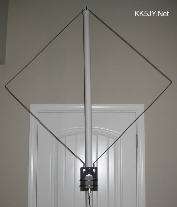
Figure 17: Loop Element
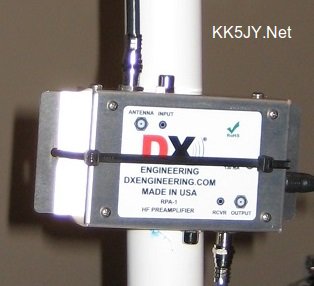
Figure 18: RPA-1 Preamplifier
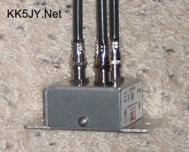
Figure 19: 2:1 Signal Combiner
The 40m version of this antenna has been constructed, and shows significant directivity at low angles, but is also responsive
to NVIS signals arriving at very high angles. The noise response is greatly reduced, even with preamplifiers, yielding
a pleasant and consistent signal-to-noise ratio.
The element shown in Figure 17 is a 30" square (10' of wire, total, per element), with a 1:1 choke balun at the feedpoint. The
choke is a QRP choke balun from Balun Designs.
I have achieved even better results, particularly on longer wavelengths, by using a Beverage
transformer in place of the choke. The Beverage transformer has some advantages over the
choke, including 100% DC isolation of the antenna from the feedline. The design I use is
the same design described by W8JI for his Beverage
antennas, which is the same design used by DXE for their
commercial version of the same device.
The feedline is Belden 8241 (RG-59) 75-ohm coax. I chose this
cable because it is one of the few 75-ohm cables that has a solid dielectric, rather than foam. The hope was to avoid water
intrusion, although newer flooded cables have excellent water resistance when used with appropriate connectors. Also, the 8241
has very detailed specifications available, whereas RG-6 or RG-59 from the local home improvement store may be hard to characterize.
Having accurate specifications with respect to the cable's velocity factor
is very important for cutting accurate delay line lengths.
Each element has a mast-mounted preamplifier. For the first draft, I chose the
RPA-1 from DX Engineering, because it has excellent IP3 and low-signal
characteristics. There are, however, many different preamp kits available that can work just as well and are far less expensive.
DXE currently sells such kits, alongside their RPA-1.
The signal combiner is a DXE RSC-2. This is a two-port passive
splitter/combiner module, impedance-matched for 75-ohm cable. The combiner needs to be impedance-matched to the delay lines
and to the preamplifier output, to ensure low SWR within the delay lines. This preserves the antenna pattern by eliminating
reflections within the delay-producing feedlines. An active combiner could also be used, and it could be something as simple
as a single RF op-amp used as an additive mixer. If an active device is used, the same rules apply -- the mixer inputs must
be impedance-matched to the feedlines to avoid reflections.
I am using coaxial delay lines alone to set the delay value. This involves cutting lines that have a specific electrical
length. Rather than cut a single cable for each band, I made a set of "jumpers," whose lengths are the set of a
binary series: 6", 1', 2', 4', 8', 16', 32' and so on. This allows any delay line length to be easily constructed with
inexpensive barrel connectors, and adjustment of the line length can be done easily by adding or removing a segment. A more
flexible solution would use a phasing controller such as the DXE NCC-1. This would allow instant reversal of the direction
of the antenna, and more precise fine-tuning the pattern for best directivity and response. Given that this is a $600 device,
I am happy to use the less expensive option for now. Reversing the direction of the antenna involves swapping which antenna
is fed by the longer line.
Using EZ-NEC 6.0, I was able to determine the average gain and compare it to the maximum gain
of the antenna. Using the
W8WWV formula
for RDF, I calculated the RDF for 40m and 80m to be 9dB and 9.2dB, respectively. This is on par with a
well-designed beverage over 300' long.
Tests are ongoing, but the initial results are very promising. The effective performance on 40m is good enough to be compared
to a 2-element beam antenna. The difference here is that this beam antenna can easily fit inside a house or attic space,
and maintain its DX-friendly performance. I have also experimented using a single element without a
preamplifier, which can give nice bidirectional performance, and features a much simpler feedline system.
My main goal for these antennas is to use them for reception of the lower bands (40m, 80m and 160m), to obtain better S/N performance
than can be achieved from typical resonant transmit antennas. This should allow me to optimize the transmit and receive antennas
independently, to get the best performance from each. Since effective receiving antennas are the most difficult on the low bands,
having the flexibility to pick the best antenna for TX and RX independently is a nice alternative to having to
build a huge tower
to support combined TX/RX antennas that can fill both roles well. As the various suburban noises come and go, I expect to find
that sometimes it will be nice to have a low-band receive antenna performance on higher bands, like 20m, as well.
Copyright (C) 2016-2017 by Matt Roberts, All Rights Reserved.