The Loop on Ground Antenna

Matt Roberts - matt-at-kk5jy-dot-net

Published: 2016-04-10

Updated: 2024-03-30


Antennas made from conductors installed flush with the ground are not a new idea.  The Beverage antenna is an example of an antenna that is typically installed within a few feet of the ground, but as a special case, it can also be installed directly on the surface — an arrangement called a "Beverage on Ground" or "BoG."  The Beverage antenna is not the only antenna type that can be installed close to the ground.  Other more conventional antennas can be installed on the ground in order to obtain specific performance characteristics.  Such installations can be used effectively for the reception of HF skywave signals at all arrival angles.

When a horizontal antenna is installed on (or very near) the surface, its primary response is vertically-polarized, rather than horizontally, because the ground reflection cancels essentially all of the horizontally-polarized wave response.  The elevation-plane response becomes nearly uniform from the horizon to directly overhead.  While a dipole antenna mounted on the ground is perhaps the simplest such design, other shapes can be used effectively for reception.  In particular, the loop antenna can be a very space-efficient ground-mounted antenna for reception on the low-bands.

The proximity of the wire to the ground makes such an antenna very lossy, rendering it rather useless for transmission.  For reception, however, a lossy antenna can be a serious asset, and the pattern and directivity very helpful, especially at longer wavelengths.

The Prototype

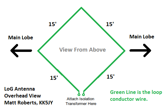
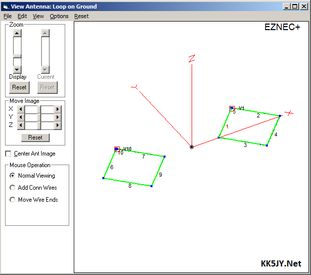
The prototype antenna is a corner-fed square loop, 15' per side, mounted at ground level, and constructed with insulated wire.  For now, I am taking a cue from the Beverage community, and calling this a Loop on Ground, or "LoG" antenna.  The EZNEC model for this antenna is shown in Figure 1, with an overhead view in Figure 2.

LoG Antenna
Figure 1: EZNEC Antenna Model (3D View)
  LoG Antenna
Figure 2: Antenna Diagram (Overhead View)

This antenna has demonstrated very effective reception at both high and low angles.  This makes it particularly useful on the longer wavelengths, where both domestic (high-angle) and DX (low-angle) signals can be received at the same time.  (For examples, see the sidebar, Testing the Loop-on-Ground with Real Signals, below).

The S/N observed is excellent, even in the presence of convective weather, while DX and domestic stations appear with similar S/N.  The aperture of the loop is more than sufficient to allow the antenna to set the noise floor of an average receiver, without the use of an outboard preamplifier.  This is an important feature, because each additional amplifier in the receiver chain, including each outboard preamplifier, raises the noise floor a bit.

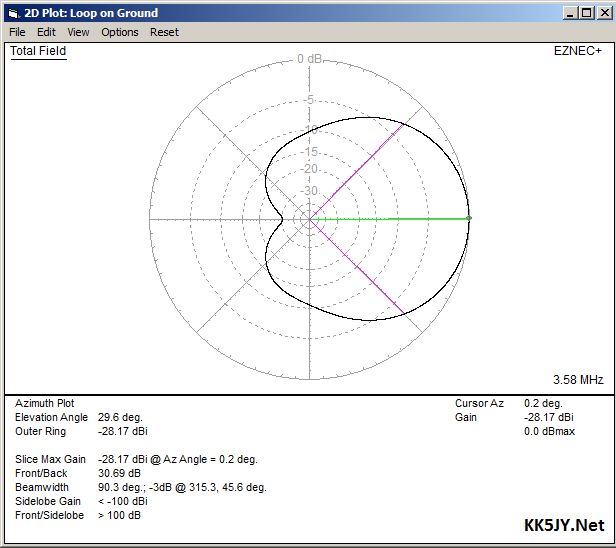
The azimuth response of a single loop element is bidirectional at low angles, slowly becoming unidirectional with increasing elevation angle.  This is similar to a dipole or small vertical loop antenna, or an unterminated Beverage.  If unidirectional reception is desired, two elements can be easily phased to provide response similar to a terminated Beverage or beam antenna, and this is described in the Unidirectional Reception section, below.

6.25:1 Transformer 6.25:1 Transformer 6.25:1 Transformer
6.25:1 Transformer
The coax run from the antenna to my operating position is just shy of 200' of (mostly) 75-ohm cable.  Since this antenna is not resonant (by design), cable selection is not critical.  A good-quality, low-loss 75-ohm CATV cable should be more than sufficient for most installations.  Since waterproof versions of such cable are readily and cheaply available, it makes an ideal low-cost option.

The antenna itself is not grounded, and it uses an isolation transformer at the feedpoint.  This provides a near-short circuit at DC on both sides of the transformer, while DC-isolating the antenna from the cable.  This isolation also helps greatly to preserve the pattern of the antenna.  The coaxial cable shield is grounded at the building entry point, providing lightning and static immunity similar to that of a properly constructed Beverage antenna.

The isolation transformer used at the feedpoint is a home-made device, mounted in a compact enclosure (Hammond part #1551RBK) which is easier to install flush with the ground.  The transformer is wound on a Fair-Rite #73 material binocular core (datasheet), which is about 1.5 cm square.  The #73 material datasheet shows that it is optimized for frequencies roughly in the range of the 160m through 30m amateur bands.  The transformer uses two turns connected to the coax, and five turns connected to the antenna (see schematic at right).  The core is quite small, so use of fine wire is necessary, such as enameled magnet wire, or teflon-coated wire-wrap wire, with #28 or #30 AWG being about the right size.  If larger wire is desired, a larger core should be selected.

The transformer is essentially the same design used by W8JI for his Beverages, which is the design used by DXE for their very nice commercial version, and shows similar performance across the lower HF bands.  The custom enclosure, shown at right, measures about 2" square and less than an inch thick.  Unlike the DXE design, I chose to mount the F connector on the side of the enclosure so that the 75-ohm cable can be run completely flush with the ground.  This transformer design is very economical, with core, enclosure, and connector hardware coming in at about $5 US, total.

Related:  Beverage Transformer FAQ

I didn't want to trip over the loop wire, nor did I want the lawnmower to eat it, so the easiest solution for "attaching" it to the ground was to simply pin the wire and feedline to the dirt using common landscaping staples.  These are nothing more than U-shaped pieces of wire that are used to hold down plastic sheeting and irrigation hose for landscaping purposes.  Since the loop antenna itself is built with insulated wire, the staples need not be insulated.  Simple steel staples are available at any big-box hardware store, or from DXE, but they can also be easily crafted from fence wire by simply wrapping a few inches in a half-turn around a screwdriver shaft.  I stapled down the wire, feedline, and transformer using one staple every 18" to 24" along the wire and coax.  This was more than enough to prevent a tripping hazard, and kept it out of the mower blades.  After a few weeks, the Bermuda runners had completely covered the antenna.

The Model

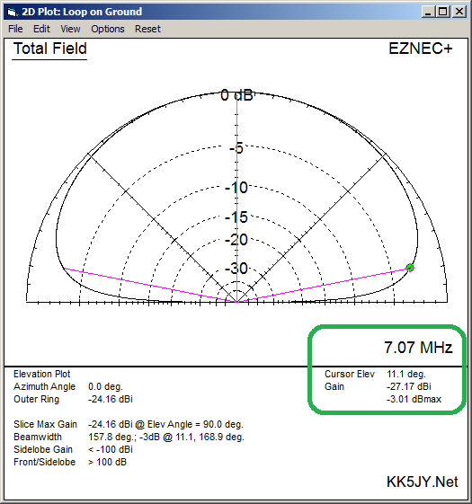
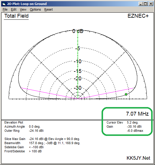
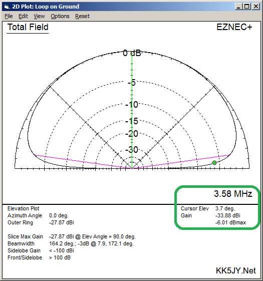
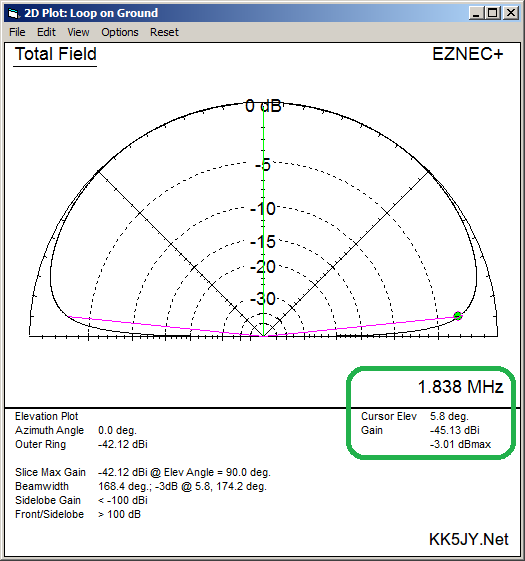
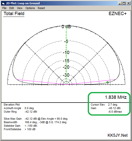
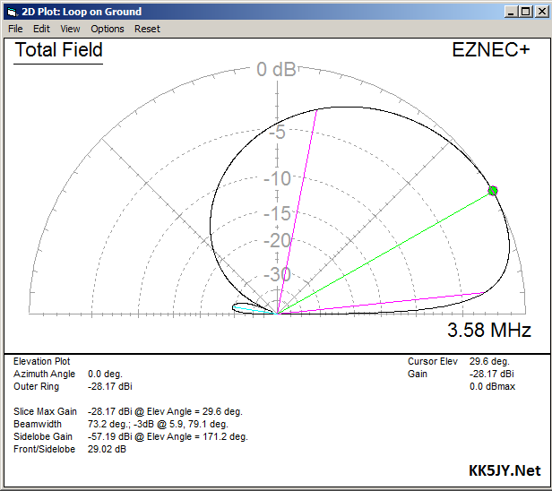
My work on this antenna started with computer models.  The EZNEC+ elevation plots of this antenna are shown below on several bands.  Note that the -3dB and -6dB points in the elevation response are at very low angles, even lower than many full-sized verticals achieve over similar ground.  For each band, the left-hand plot highlights the -3dB elevation angle (indicated by the green dot on the trace), and the right-hand plot highlights the -6dB elevation angle.  The -3dB angle is where the gain is one-half of an S-unit down from the overhead peak.  The -6dB angle is where the gain is expected to be one full S-unit down from the overhead peak.  The frequency, elevation angle, the absolute gain (dBi) and the antenna-relative gain (dBmax) are highlighted in a green box on each plot.

Click on any plot to enlarge it.

40m Elevation Plane  40m Elevation Plane
Figure 3: 40m Elevation Plane

80m Elevation Plane  80m Elevation Plane
Figure 4: 80m Elevation Plane

160m Elevation Plane  160m Elevation Plane
Figure 5: 160m Elevation Plane

Experimenting with the model, it appears that the best DX pattern, with lowest -3dB elevation angle, is obtained with a loop whose side total length is approximately 15% of the target wavelength.  The 60' overall length of the prototype loop was a rough estimate of a loop that would be a good compromise across the 40m, 80m and 160m bands.

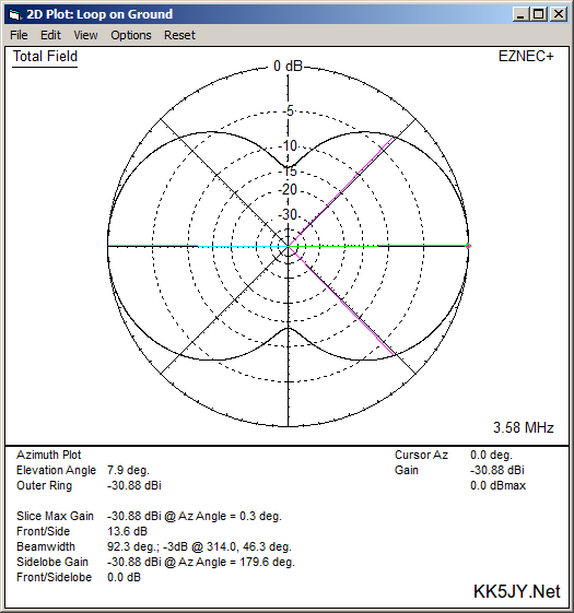
The direction of maximum azimuth response, at low elevation angles, is normal to the feedpoint.  For example, if the square loop is arranged such that its sides face the cardinal directions of the compass, and fed at the NW corner, the strongest azimuth response is to the NE and SW.  Experimental results confirm this behavior.  The loop can be fed at a corner or on a side, whichever gives the desired response.  The loop doesn't even need to be a square.  The square tends to be simplest to set up, but an octagonal or circular loop should also work just as well.

At higher elevation angles, the antenna quickly becomes omnidirectional, so higher-angle signals can be heard at any bearing.  This can also be helpful if you intend to use the loop for regional contacts inside the skip zone.

The -3dB azimuth beamwidth at low angles is approximately 90° in each of the two main lobes, as shown here for the 80m response at 8° elevation, fed at the 12-o-clock position of the loop.

80m Azimuth Plane
Figure 6: 80m Azimuth Plane at 8° Elevation

Unidirectional Reception

If a unidirectional pattern is desired, this antenna can be deployed in a pair, separated by as little as a single loop diameter, to form a phased array.  An example pair for 80m is shown in Figure 7, constructed with two 15' loops separated by one loop diagonal, and phased with a ~130° delay line.  The end-to-end length of the installed array is approximately 61', which can fit in many suburban yards.  Note that the lower -3dB elevation angle is around 6°, which should be excellent for DX reception, while still preserving sensitivity at higher angles which can be used for hearing domestic stations.  The total -3dB azimuth bandwidth is approximately 90°, which is 45° either side of the centerline of the array.

80m Model 80m Phased Array Elevation Plane 80m Phased Array Azimuth Plane
Figure 7: 80m Model and Pattern Plots
for Two-Element Phased Array


For more information about building phased pairs of antenna, please see this article about the subject.

When carefully constructed, an array such as this can have the directivity (RDF) performance of a large beam antenna at significant height, or a long terminated Beverage antenna.  This antenna, however, can be completely invisible in the yard, and consumes a fraction of the space.

Testing the Loop-on-Ground with Real Signals

In a recent RTTY contest, I watched as a friend did a CQ run on 40m.  He was using a full-size 33' 40m vertical at his station, which has similar ground elevation to mine.  Since our stations are also within a few miles of each other, this allowed me to watch him work several stations in quick succession, while I observed his run on the LoG antenna.  In order to compare the receive performance of the two, I watched to see how many stations he could hear on the vertical that I could not hear on the LoG, and vice versa.

The vast majority of stations that he worked were also perfectly copied on the LoG.  There was one station that he heard that was marginal copy on the LoG.  Surprisingly, there were several stations that I could copy perfectly on the LoG that he never heard on his vertical.  He called CQ, and they answered him, but he just couldn't hear them.  I looked up those stations to find their location, and none of them were inside the skip zone, or anywhere near it.  In fact, the stations he was missing were all on the order of 1,000 to 1,500 miles away from him.  Because of the pattern differences at high angles, you would expect the LoG to hear close-in stations better than the vertical, but these were not NVIS signals.  These were low-angle skywave signals that the LoG simply heard better than the vertical.  So at least for this one test, the 15' square LoG antenna actually pulled in more stations on receive than his full-size vertical antenna on 40m.  When we both switched to 80m, I was able to copy several stations, while he couldn't hear anybody.

Log on 160m Panadapter
Log on 80m Panadapter
Since then, the LoG has acquitted itself nicely in several 80m and 160m contests.  The recieved S/N ratio often looks better than 15m on my hexbeam, and screen captures of the panadapter can be seen at right.  The top image is from a 160m CW contest, and the other is from an 80m RTTY contest (click to enlarge).

The LoG serves as the sole receive antenna for these bands, driving both the TS-590SG and an SDR dongle used as a pandapter.  The antenna produces enough signal to "set the noise" in both the panadapter and the transceiver, even with the 3dB splitter loss.

Not only am I able to work contests despite my challenging suburban RF environment, I greatly enjoy listening to clean and low-noise CW and RTTY for the long hours of contest operation.  The LoG easily hears stations at all distances, from a few miles to many hundreds of miles, all with similar S/N levels.

Contest operation is one thing, but I also decided to take advanatage of all the recent FT8 activity to test the antenna on normal HF traffic.  On a random July evening, I used a RTL-SDR connected to the loop-on-ground to listen to 40m traffic overnight.  The RTL-SDR is a very inexpensive and popular reciever, but it is not well known as a high-performance device.  My hope was to demonstrate what could be done with the LoG when paired with an "average" receiver.

The resulting 24-hour map is shown below:
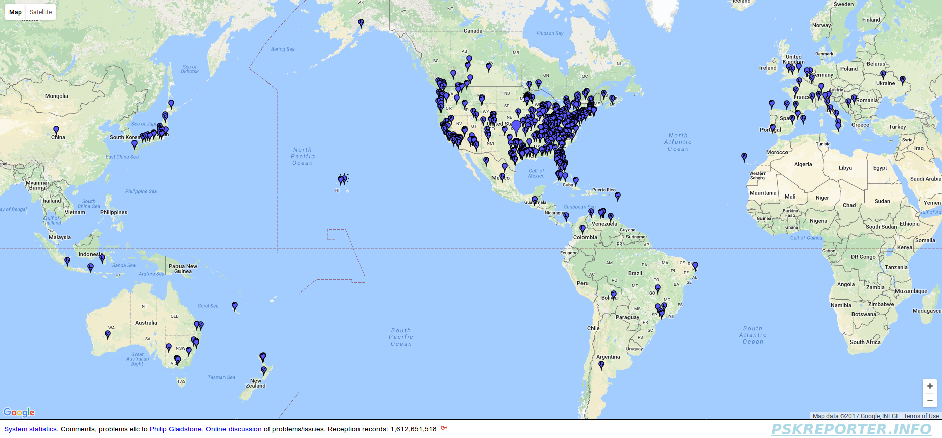
The antenna not only pulled in dozens of US stations at all distances, but it was able to hear DX from Japan, Australia, Europe, South America, and even China.  Japan alone produced over two dozen spots.

The JT-mode activity on 80m isn't nearly as crowded as 40m, but a recent 24-hour map of the same three modes on 80m showed that the antenna has solid coverage across North America, with DX coverage into Europe, Japan, South America, South Africa, Australia and the South Pacific.

I am starting to hear from people who are using larger LoG antennas for reception on the new 630m band with results that are similar to my tests on 40m, 80m, and 160m.

The performance of the antenna is clearly up to the task of both DX and domestic HF reception, even with the most modest of receivers.
Practical Considerations

As low-band receiving antennas go, a 15' square is hard to beat for space efficiency.  There is nothing special about the 15' figure, either.  I have modeled this antenna at several different side lengths, from 5' per side to 60' per side, and the main trade-off appears to be pattern shape on shorter wavelengths, versus signal strength on the longer wavelengths.  Generally, longer wavelengths tend to have better low-angle pattern coverage, possibly due to the increased skin depth of the ground at these wavelengths.  This makes the loop antenna a more natural option for the lower bands than the higher bands.  In practice, the 15' square antenna produces generous signal levels on the lower contest bands: 40m, 80m, and 160m.  It produces similar gain levels on 40m and 80m, and similar noise floor level across all of the bands where I have used it.  The gain increases with increasing frequency, which means that very little adjustment needs to be made to receiver gain when changing from one band to another.

After a year in the yard, I pulled up the original loop and its matching transformer, in order to move the antenna and change its orientation a few degrees.  Before putting the loop back down, I opened the custom transformer enclosure to see how it was resisting water intrusion.  A year in the yard had caused the box to be completely buried in dirt and covered by sprigs of grass.  To my surprise, the enclosure had only a very small amount of condensation on the inside of the lid, which was facing down into the dirt.  The rest of the inside of the enclosure was dry and clean.  I carefully applied some silicone dielectric grease to the edges of the open box and around the holes I had drilled for wires, reassembled it, and then installed the antenna in its new location.  I was very happy with the enclosure's ability to keep water out (and more importantly, to keep dirt and other debris out).  The enclosure's design provides a precise and tight fit, and it turned out to be a good choice for a ground-mounted RF transformer.

Advantages

When compared to a classical Beverage antenna, the LoG antenna can offer similar RDF performance, but in a much smaller space, and without obstructing other use of the affected property.  This can be a real asset to people who have had their Beverage antennas destroyed by deer antlers, or who have had enormous areas of property made otherwise unusable because of the dangling Beverage wires.  A single LoG element approximates the performance of an unterminated Beverage antenna, while a two-element phased array of LoG elements approximates the performance of a terminated Beverage.  In both cases, the LoG is a fraciton of the size of the corresponding Beverage antenna.

Unlike the Beverage, the LoG does not require use of the ground as part of the electrical circuit.  Any Beverage requires ground rods be driven at the feedline end, and a terminated Beverage requires more rods be driven at the termination end, in order to use the ground as part of the circuit.  The LoG does not require connection to the earth beneath it, and actually benefits from being well-insulated from the ground.  As a result, the loop can be installed anywhere without regard to whether grounding is availble or even possible in that location.  This makes it perfectly usable above buried utilities or yard irrigation systems.  This also makes the LoG easy to move, since relocating the antenna involves no more than pulling up the wire and tacking it down somewhere else.  Obviously, yard staples are far easier to relocate than 8' ground rods.  If you want to experiment with different locations for a LoG antenna, all you need is four short tent stakes to hold it in place while you evaluate its performance.  In a single evening, one person can easily install and test a LoG antenna in multiple locations on his/her property.  This feature also makes the antenna handy for portable or temporary operations such as during Field Day.

As with all receive antennas, the main advantage is the simultaneous use of separate transmit and receive antennas, each optimizing its respective operation.  That is, use a receive antenna for the best signal-to-noise ratio while receiving, and use a transmit antenna that provides the best signal at the distant station, given the available real-estate.  If the prime real-estate for your low-band antenna is tied up with a vertical and its radial fan (as is the case at my location), antennas like this give you the opportunity to have improved performance during reception, as well, without giving up your preferred transmit antenna, or its location.

Location and Colocation

Effective Beverage antennas are completely out of the question for many of us, but to work the low bands, Beverage-like performance would be helpful when operating in our noisy urban environments.  In fact, urban operators need effective receive antennas for the low bands even more than those who actually have sufficient space for Beverages.

Many hams use a vertical antenna on the low bands, particularly on 80m and 160m, in order to fit the yard space they have available.  The loop-on-ground makes an excellent companion to a vertical, using the LoG as a dedicated recieve antenna and the vertical as a dedicated transmit antenna.  The vertical can be installed in a back yard away from view, while the LoG can be installed in a front or side yard, where it will be completely invisible, safe, and well-separated from the transmit antenna.

In my case, the best location for a receive antenna is such that it is unusable for an above-ground antenna.  This makes an on-ground antenna ideal, because I can tack it down in the grass in the best location, while placing the transmit antenna where its installation is more practical.

Even for people with a generous piece of property, this kind of antenna allows the yard containing the receive antenna to be used for other purposes.  When installed carefully, the kids can play soccer right over the top of it and never know the difference.  As a receiving antenna, it is completely RF-safe.  Since the size and shape are not critical, otherwise unavailable pieces of a yard can be purposed to hold a low-noise receive antenna.  Such areas could be the corners of a yard that surrounds a pool, or the area around a decorative tree.  This kind of device would be well-suited for any landscaped area that is maintained for aesthetic purposes.

A loop antenna covered by the lawn is the very definition of a stealth antenna, which should make it very attractive for people living with antenna restrictions.  Combined with its small size, the loop-on-ground design might make an effective low-noise receive antenna for people who live with a combination of a small lot and land use restrictions (particularly the family-imposed restrictions ;).  The fact that the antenna has no support structure means that it shouldn't run afoul of most building restrictions.

A Note on Preamplifiers

During the CQ 160m event (see the sidebar at right), I experimented with making QSOs both with and without the 590's preamplifier enabled.  When run on 80m or 40m, this antenna needs no preamplifier, as long as quality feedline is used (e.g., RG-6 or RG-8X).  Even though the pattern gain on 160m is nearly 15dB below that on 80m, a preamplifier still wasn't necessary for making any 160m contacts.  While the preamplifier did seem to raise some of the weaker signals a bit, there were no stations that were so weak that they required use of the preamp.  So the use of a preamp with this antenna is probably a matter of taste for each operator.  If a preamp is desired for 160m operation, the preamp built into any modern transceiver is more than enough.

My personal preference, even on 160m, was to run with the preamp off.  On all bands I have tried, from 160m through 20m, the antenna produces enough signal so that the atmospheric noise can easily be heard in the receiver.  Since the noise floor is set by the antenna (rather than the receiver), I prefer to listen to the band as quietly as possible, which means no preamp.

Remember, as with any receiving antenna, if you hear an increase in band noise when you connect the antenna, and a decrease when you disconnect it, the antenna has enough gain for that band, and a preamplifier is unnecessary.  You might need to turn up the volume to get the sound level you want, but if you can run without a preamplifier, it will improve the SNR in your receiver.

Larger Antennas

Several people have written to me to ask about making a larger LoG antenna than the 15' square that I am using.  These have been people who tend to have large lots with plenty of extra space, such as at a rural home, or farm or ranch.

For any given frequency, making any small loop antenna larger will certainly increase the signal level.  Whether this is helpful depends on the site details.  If you connect the antenna to a running receiver, and the noise level goes up when you connect the antenna, and down when you disconnect it, you already have enough signal, and the antenna is large enough for that band.  Even if the S-meter doesn't change, the goal is for the antenna to set the background noise level, and not the receiver.  Since the loop isn't resonant, its size isn't critical, per se, as long as the loop is laid out on the ground in a symmetric pattern relative to the feedpoint axis.

A larger loop can be particularly helpful for operations on very low frequencies, such as 160m, or one of the new 630m and 2200m bands, where wavelengths are enormous.  If you have the space to make the LoG larger, these bands may benefit from the extra signal level provided by a larger loop.   Many receivers have reduced sensitivity on the LF bands, so capturing more signal could help get the atmospheric noise level above the receiver noise in such a receiver.  Given the challenges of constructing any kind of effective antenna for the new LF bands, the LoG can be a welcome alternative to using a vertical or a large Beverage for reception on those bands.

Where larger loops become a problem is on higher bands.  I regularly use my LoG antenna on 160m through 20m, and at 20m, the 15'-per-side is approaching 1·λ in circumference.  As the antenna approaches 1·λ, the pattern of the antenna starts to lose its symmetry, and the main lobes start to drift from the pure side-to-side shape, and start to point in other directions.  This effect is well-known to users of elevated horizontal loop antennas, because on bands higher than the fundamental of those loops, the loop starts to generate nulls and peaks in unintended directions.

As a result, I recommend that you use a loop that is no more than one electrical wavelength in circumference, adjusted for the insulation of the wire, on the shortest wavelength on which you intend to operate.  As a rule of thumb, this gives a physical length that is perhaps 90% to 95% of 1·λ on that band.  A loop with 15' per side should resonate somewhere between 15.5 and 16MHz, so this approach suggests that my loop is OK for 20m and longer wavelengths, which has also been my experience when operating on the air.  To calculate the circumference of a 1·λ loop, just use L = 936 / f, where f is the highest frequency you intend to use with the loop, and then keep your loop circumference smaller than the calculated value L.

Obviously, this means that a loop installed exclusively for 160m use can be twice as large as a loop installed for both 160m and 80m, and four times the size of a loop that is intended for use on 160m through 40m.  I have found that a loop 15' per side is enough to cover 160m through 20m very comfortably from my QTH.  In a rural environment, one might wish to use a loop that is 30' per side, to provide increased signal strength on 160m, at the cost of 20m pattern shape.

If you find that you do have room for a very large loop, it is worth considering putting out two loops, one larger than the other, if you want to operate across several bands.  Use the larger one for the lower bands, and the smaller one for the higher bands.  This helps preserve the loop pattern and performance.  If you want to use a large loop on a shorter wavelength, I recommend that you model it first, so that you know what the pattern will look like.

The Bottom Line

Now that the antenna has been in the yard for a while, I have been able to test it on some real-world signals, as described in the sidebar at right.  This is where the rubber meets the road, because my home is located in a less-than-friendly RF environment.  Nonetheless, I am very pleased with the results of the 15' square loop-on-ground, and it has become my primary recieve antenna for most HF work.  Since we are well into the low-band years of the sunspot cycle, this antenna appears to be well-sized for this kind of on-air work.  In the end, a loop of wire in my yard has turned out to be one of the best pieces of gear I have ever used for HF, as well as one of the least expensive.  That's a slam-dunk combination.


Copyright (C) 2016-2023 by Matt Roberts, All Rights Reserved.