AutoCap Firmware for Arduino

For Small Magnetic Transmitting Loop Antennas

Matt Roberts - matt-at-kk5jy-dot-net

Published: 2016-09-17

Updated: 2016-09-18


Introduction


The AutoCap project includes custom firmware for Arduino, that the AutoCap software can use to control a DC gearhead motor or a stepper motor with great precision.  While originally developed for this purpose, the firmware has enough flexibility to be used in isolation, without a computer at all, to provide manual control of a motor-driven capacitor of a small loop antenna.

This article describes the use of AutoCap firmware without PC software, with several hardware options not normally needed when under PC control.  These options allow you to manually perform the same kinds of motor operations that the AutoCap desktop software uses when doing automatic adjustment.  The firmware described below is the Version 1.5 development branch, which can be used with or without a host PC, and is fully compatible with the AutoCap software.  The Version 1.5 firmware can be configured to support several user interface elements, such as an LCD or LED display, button inputs for motor control and unit configuration, and of course, you can add any number of blinking LEDs that you like. ;-)

Figure 1: Complete Kit
User Interface

The Version 1.0 firmware supported hardware button inputs for port selection and continuous movement commands.  The Version 1.5 firmware extends this into a complete user interface that supports the following: The user interface (UI) allows a standalone Arduino with appropriate hardware to control a loop-attached motor with the same precision as can be accomplished from the AutoCap UI on a host computer, but without the host computer.

A fully equipped unit is shown in Figure 1, without an enclosure, to show all of the components, including an OLED display, buttons, and motor interface board (dual h-bridge).  In this example the H-bridge is configured for a single stepper motor in a standard four-wire arrangement.  This hardware configuration consumes almost all of the I/O pins of the UNO, and most of its flash storage.  If I want to add more motors, more LEDs, etc, I need to move to a board with more I/O lines, like the Arduino Mega, which is designed specifically for more elaborate user interfaces.

In this example, the OLED display is connected to pins D6 through D12, and the IN0 and IN1 lines of the H-bridge board are connected to pins D4 and D5, with IN2 and IN3 connected to A4 and A5.  Each of the four H-bridge inputs has an LED attached to make debugging easier (and the project more fun to watch as it runs).  The ENABLE pins from both H-bridges are connected to pin D3, which is a PWM pin.  This allows the firmware to control the motor current.  The buttons are wired to A0 through A3, which are UP, DOWN, STOP, and MODE, respectively.  Since there is only one motor, the PORT SELECT function is not configured.  The firmware allows a "heartbeat" LED to be configured, so I assigned this function to D13, which drives the LED built onto the UNO board.  This function blinks the LED once per second, to show that the firmware's main loop is operating properly.

Figure 2: Operation Selected
 
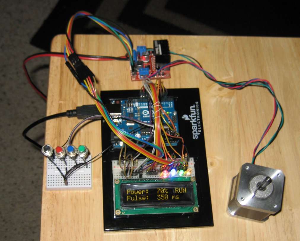
Figure 3: Motor Running
 
Figure 4: Modify Setting
The firmware supports an LCD or OLED display to be configured, and so I chose a 16x2 OLED display.  There are plenty of LCDs available with all kinds of backlight options, but a yellow-on-black OLED has much better contrast than any of the LCDs, and just looks great.  This part is available in several different colors, but the yellow version is easy to read and still easy on the eyes.  Vain appearance considerations aside, another reason I prefer the OLED displays over LCDs is that the OLED response is much faster than the LCDs.  So fast-moving changes on the display are more visible with OLED than with LCD.

The display shows the current status, including the current power level, and operating mode.  See Figure 2.  The Power value is the motor effort, specified as a percentage.  If the attached motor is a DC motor, the effort is the PWM duty cycle.  If the attached motor is a stepper motor, the effort is the step rate, as a percentage of the maximum stepper speed configured in the firmware.  Whenever the motor is moving, the top-right corner of the display will show RUN, as shown in Figure 3.

The bottom row shows the current operating mode, or a configuration setting.  By pressing the Mode button, the operating mode will move between several choices:
Normal
Momentary continuous movement - the motor starts when you press UP or DOWN and stops when you release the button.
Latched
Latched continuous movement - the motor starts when you press UP or DOWN and continues until you press STOP
Pulse
Timed pulse generation - motion starts when you press UP or DOWN and stops after a configurable delay
Step
Fixed step generation - motion starts when you press UP or DOWN and stops after the motor moves a configurable number of steps.
These different motor operations can be modified by changing settings.  If the Mode button is pressed and held for more than one second, the bottom line of the display will show one of the motor settings, and each additional momentary press of the Mode button will cycle through the other settings:
Power
This sets the PWM level for DC motors, or the step rate for a stepper motor; in either case, this controls the motor speed.
Pulse
The pulse duration, for timed pulse generation, measured in milliseconds.
Steps
The step count, for fixed-step pulse generation.
For any setting, you can adjust the value by pressing UP or DOWN to select a new value.  Some reasonable limits are observed on the range of values.  Pressing and holding the Mode button will return the display to an operational mode.  When in a configuration mode, an asterisk (*) appears in the bottom right of the display, as shown in Figure 4.

When you enter or leave a configuration mode by holding Mode, the corresponding operation mode will be selected.  That is, if you are in Pulse mode, and press and hold Mode, the unit will show the pulse duration setting, since this is the setting most closely applicable to the operation mode you were using.  You can still tap Mode to select another setting, but the idea is that the UI tries minimize the number of buttons you have to press to "tweak" a setting.  Note that the motor can only be commanded using the UP or DOWN buttons when an operational mode is selected.  When in configuration mode, the UP and DOWN buttons are used to change configuration values.

The firmware can be configured to persist its state, so that when it is powered off and back on, it will remember what settings were entered.  This is an option that must be enabled in the firmware, and it is also requires a firmware initialization step, that must be done one time via computer.  With a terminal or the Arduino serial monitor running, a new device should be programmed with the firmware, and then the F and W commands issued.  This does a "factory" reset of the EEPROM, followed by a "write" of a complete configuration block to the EEPROM.  This only needs to be done once, when first constructing your device, and can be done as soon as you flash in the firmware.  After these steps are done, the device will update the EEPROM after about 10 seconds of UI inactivity, after a setting is changed.  This delay is intended to maximize the life of the EEPROM, but still be responsive to state changes.

Hardware Notes

The main sketch code contains many comments intended to guide you in configuring the firmware for your specific hardware.  The code contains a specific warning which was hinted above, and should be repeated here.  The Arduino UNO is a nice device, but it does have limited resources, specifically a limited number of I/O lines, and a limited amount of RAM and Flash.  Every feature you add to the firmware requires more program code, and more RAM, and every device added requires more I/O lines from the board.  If you want to add more devices than you have pins available, consider an Arduino Mega, which has many more I/O lines, and four times the RAM of an UNO.

One way to free up some I/O lines in a "fully loaded" unit is to trade the OLED or LCD unit for one that supports I2C, also known as TWI.  Most LCD and OLED devices require seven or more I/O lines, whereas a TWI device can get away with just two signaling lines.  This will free up more I/O pins to use for motors.  There are adapters available that will convert any HD44780-driven LCD into an TWI or SPI device, that can be integrated by simply adding the vendor-provided library, and updating the display definition.

Conclusions

The Version 1.5 firmware is still under active development, so the default display details may change as I work out an improved workflow.  The source code is well-commented, so you can modify it to display whatever you want.  The current options of the firmware already support stand-alone remote-tuned loop operation with a single Arduino.

Firmware Downloads


The firmware source code is available in the Downloads area of the area of the AutoCap project.  Make sure to use the firmware Version 1.5, which contains the complete user interface support.  Since the Version 1.5 changes are relatively new, the older Version 1.0 firmware is still available.

Links

Arduino - Open-source hardware and embedded development tools.
SparkFun - Good source for Arduino and robotics hardware.
AdaFruit - Another good source for Arduino hardware.

Copyright (C) 2014-2016 by Matt Roberts, All Rights Reserved.