A summary of the the construction details of a multiband dipole that can can operate
at high power levels, and match its 50-ohm coax feedline without a tuner.
Previous Work
This antenna system is based largely on previous work done by amateurs for decades,
using feedline segments of carefully-selected length for matching two feedlines of
different characteristic impedance. Specifically, I built upon the work of
W5DXP
who built a similar system, and used relays to select the window line length desired for
matching. His project used series transformer sections exclusively. The main change
I made here was to use a combination of series and shunt segments.
Early Versions
A horizontal dipole is a very well-studied device. I won't belabor the details
here. However, my current dipole is the result of a series of experiments in
horizontal dipoles of varying heights, lengths, and orientations. Each revision
was rather successful, and encouraged me to continue to improve the design. Each
version was constructed from #12 stranded, THHN-insulated wire, fed with 300-ohm
window line, and matched with an
SGC-230
at the base of the window line, to attach to a coaxial feedline that led into the
house.
The current design is a result of my desire to run high power (QRO) on this dipole,
without having to invest in a QRO outdoor/remote tuner. Even the SGC-230 is quite
pricey, and it has a 200W/80W SSB/CW power limit. Remote tuners that can handle
higher power are unbelievably expensive. It's not hard to see why, because the RF
voltages and currents inside the tuner's reactive elements can be blisteringly high
at kW levels, even with mismatches lower than 10:1. The SGC-230's manual warns that
RF voltages at the antenna terminals can reach several kV for high-Z antennas.
One of the last upgrades to the dipole before experimenting with high-power tuning
was to change the 300-ohm window line to
600-ohm ladder line.
The higher-Z open-wire lines experience less loss overall, which means that they can
operate at higher SWR than the lower-Z lines for a given loss value.
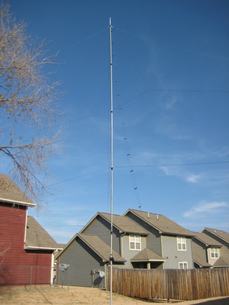
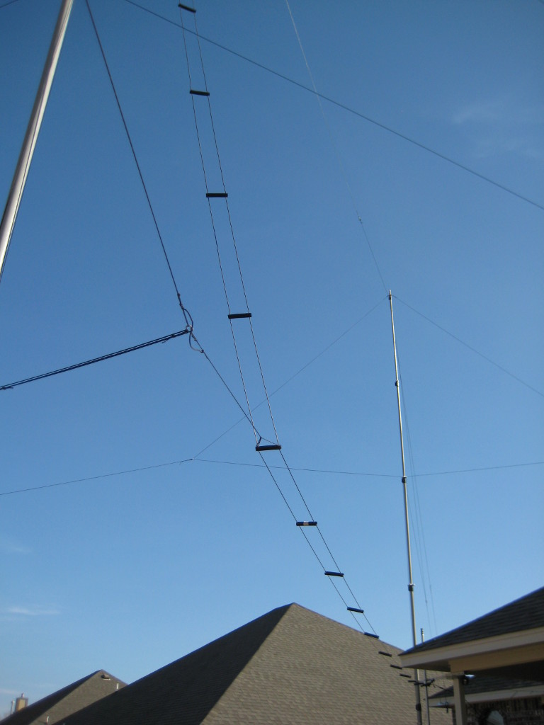
Here is the result, a dipole with slightly elevated center support, 45' overall
length, 35' high in the center.
The 45' length was chosen to accomodate frequencies 30m and above, fit well inside
my small suburban back yard, and squeeze as much gain as possible from the antenna.
At the same time, the antenna was kept short enough so that the main lobes at the
highest frequency of interest (10m) were still normal (perpendicular) to the wire
axis itself. The 45' length was the longest overall antenna that would meet these
constraints.
A Little Planning
Any simple multiband dipole (i.e., those that employe a single conductor, and no
traps) will offer an
impedance that is widely different from 50-ohms, for most of the desired frequencies
of operation. Some multiband dipoles are deliberately designed to offer a large mismatch
on all of the desired frequencies of operation, in order to optimize certain bands, or
to minimize the SWR on the largest number of bands. In any event, the the multiband
dipole is not suitable for connection to coaxial cable, if low losses are desired.
The advantage to using a remote tuner between the coaxial feedline and the window
line is that the high-SWR operation is limited to the section of window line, where
the additional SWR-induced losses are much lower than they would be in an equivalent
length of coaxial cable. Inserting a tuner at this point allows the tuning elements
to be placed at ground level, which is far easier than trying to mount it at the top
of a tower or mast. At the same time, the coaxial cable runs at very low SWR, keeping
the feedline losses low.
So the most desirable path forward is to find a way to perform high-power, multiband
impedance matching between the coax and the window line. This maximizes the actual
power delivered to the antenna on every desired band of operation.
A Little Theory
It is well-known that two feedlines of very different characteristic impedance can
be matched to each other by connecting them together with a segment length of feedline
whose characteristic impedance is somewhere between the first two. Since the dipole
was fed with 600-ohm line, and the coaxial cable from the transmitter was 50-ohm line,
I chose to match them with 300-ohm window line. The equations for this are outlined in the
Antenna Book.
Since the 600-ohm line is attached to an antenna that rarely resonates at 600 ohms,
the impedance at the match point is also unpredictable. So an additional step was
taken to aid in the tuning process.
In addition to inserting a length of 300-ohm line between the two feeds to serve as
the "transformer" segment, I also attached a length of 300-ohm line to the
antenna side of the matching line. This open stub adds a small amount of additional
capacitance on the antenna side, to help bring the match to 50 ohms. For operation on
all frequencies above the half-wave resonant frequency of the dipole, this is sufficient
to achieve a match very close to 1:1. From a matching theory standpoint, the tuning
arrangement is somewhat similar to a pi or L network, where the stub
is the antenna-side or "output" capacitor, and the series "transformer"
section provides the transmitter-side or "input" capacitance and the inductor.
In this case, the input C and L elements are distributed continuously
throughout the transformer feedline section.
The SWR on the 600-ohm ladder line is still probably very high for any given frequency,
but the match provided by the 300-ohm segments allows nearly 100% of the power provided
by the coax to be transferred to the ladder line. Since the ladder line's overall
segment loss is quite low in the HF frequency range, the additional loss incurred by
all the reflections due to the high SWR is minimized. By providing a 50-ohm match point
at the load end of the coax cable, the high-SWR region is confined to the ladder line,
and the few feet of 300-ohm transformer segments.
The No-Tuner "Tuner"
The length of the segments needed to match the dipole depends on the frequency of
operation. It should be possible to determine the lengths needed mathematically,
but instead, I used
EZ-NEC+
to simulate the feedlines, and experimentally determine the lengths required for
each band of interest. Of course, these are approximations, so some fine-tuning
was required when the stubs were actually installed.
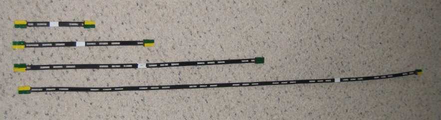
Rather than cut stubs of specific lengths, based on the models, I used another
thought from W5TXF's site, and cut several segments of varying lengths, starting
with 6", and doubling each piece's length, for 1', 2', 4' and 8' lengths,
making a "kit" that can be used to assemble any length from 6" to
16' in 6" increments.
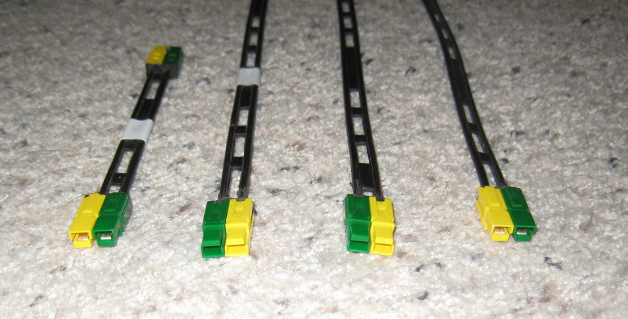
To connect the segments end-to-end, I used PowerPole connectors. In a very
convenient coincidence, the spacing between the wires of a 300-ohm line is
almost exactly the same as that between 45-Amp PowerPole pins. So these
make excellent quick-release connectors for 300-ohm line.
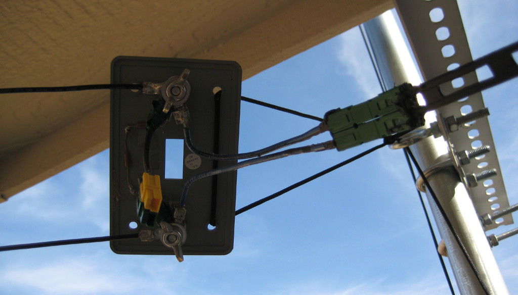
To connect the stubs to the antenna, a panel was assembled to bring it all
together. The panel was built using 1/4" hardware, installed onto a switch
plate. The switch plate is a thick, plastic, industrial-grade plate, and the
1/4" hardware is spaced to match the 600-ohm line. To this, two short
lengths of wire connect the 1/4" bolts to the two sets of PowerPoles, one
for the transformer section, and one for the open stub.
A resistor of several megaohms was placed across the 600-ohm terminals
to drain static buildup from the antenna. This is far too much resistance to
significantly alter the impedance of the antenna, but it keeps high static
voltages from building up across the antenna leads. Since one side of the
ladder line is DC-grounded through the coaxial cable (which is in turn grounded
at the house entrance panel), this arrangement will drain all static build-up
to ground before entering the house.
One of the power-pole connectors is used for the series section, and one is used
for the shunt stub. An adapter converts 300-ohm cable to 50-ohm cable, and
serves as the last few inches of the series piece. A choke is used to prevent
line imbalance from causing RF radiation or pickup from the coaxial shield.
Switching bands only requires replacing the stubs with those of the correct
length. The existing PowerPoles are simply disconnected, and the correct
lengths of window line are inserted. Starting with the lengths predicted by
EZ-NEC+, I used a
ZM-30
analyzer to fine-tune the lengths of both sections for
each band of interest. Since a 45' dipole is electrically long on all bands
at and shorter than 30m, the bandwidth was plenty wide. I found that 6"
was more than sufficient resolution to find a 1:1 match point within all of
the various CW, Data, and SSB subbands for these wavelengths.
The match panel shown above is located on my back porch. I pulled the 600-ohm
line from the antenna to the porch, and buried the coaxial feeder from that
point to the entry panel elsewhere on the back of the house. This way, I can
change the matching sections without having to go out into the yard. If I
add relays, as is the case with W5TXF's installation, I wouldn't even have
to go outside.
The ZM-30 has a nice feature that allows it to sweep through a range of
frequencies, and emit the results to a text file. That file can later be
imported into a spreadsheet for charting and analysis. I did this with
stubs of various lenghts, looking for the resonant points for each
configuration. When compared to the SWR chart output of EZ-NEC+, this
allowed me to see how the antenna model compared to the actual construction,
and it helped to refine the EZ-NEC+ model.
Summing it Up
Using this system, the coax can be matched at exactly 50 ohms on any
band from 30m through 10m. Since no lumped reactive components are used, the
matching system can be used for any power level within legal limit. At the
limit of my station, 500W, none of the components show any signs of heating,
e.g., SWR drift at high duty-cycle, arcing in or around the PowerPoles,
distortion of feedline plastics, etc.
In theory, moving to 450-ohm line would decrease the losses of the tuning
elements even further. This would be an inexpensive experiment to try. I
suspect the improvement would be negligible, since the tuning elements on
all non-WARC bands are only a few feet long.
One last point of improvement would be to add relays to switch in and out
the various segments. I have a plan for doing this using a Wi-Fi Arduino
board, or similar kit computer. That will be a subject for another article.